

PN16

BURKERT 20046486 Type 8640 modular valve island (11mm width per station, 2-bank). Features 2.5-10 bar pressure range, IP20 protection, and DIN-rail mounting for complex pneumatic control.
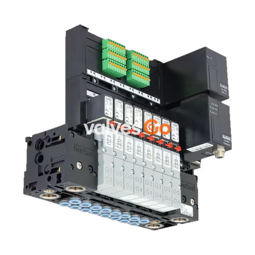
BURKERT 20046486 Type 8640 modular valve island is designed to solve diverse and complex control problems through its systematic modular construction and combination of pneumatic and electrical interfaces. By putting together a row of pneumatic modules with different numbers of valves, multiple valve functionalities may be realized on one valve unit. Bodies and connection modules are made of high-quality plastic (polyamide) and are easy to assemble by means of the built-in snap connectors.
This specific 11 mm width per station, 2-bank valve block features a 2.5 to 10 bar nominal pressure range and IP20 protection. It is designed for DIN-rail installation and utilizes bottom-positioned working connections.

| Product properties | Type 0460, Type 6524, Type 6525 |
|---|---|
| Body Material | PA (polyamide), aluminium (Type 0460) |
| Seal Material | FKM, NBR and PUR |
| Width per station | 11 mm |
| Manual override | Standard |
| Number of valve slots | 24 (Max. 12 for impulse and double valves) |
| Pressure range | Vac...10 bar |
| Flow rate QNn value air | 200...300 l/min measured at +20 °C, 6 bar pressure at valve inlet and 1 bar differential pressure |
| Operating voltage | 24 V DC (±10% tolerance) |
| Nominal power of each valve | For single valves: 0.8 W. For impulse and double valves: 2x0.8 W with power reduction |
| Degree of protection | IP20 (IP65 in closed control cabinets) |
| Working port | D 6, D 1/4 |
| Air supply connection | G 1/4, D 3/8 |
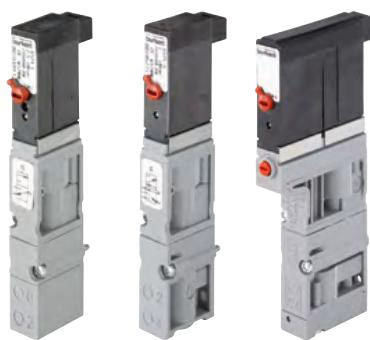
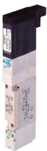
| Symbol | Description |
|---|---|
| C (CF C) | 3/2-way solenoid valve. Servo-controlled, with manual override. Normally closed. |
| D (CF D) | 3/2-way solenoid valve. Servo-controlled, with manual override. Normally open. |
| H (CF H) | 5/2-way solenoid valve. Servo-controlled, with manual override. Pressure applied via port (1), therefore one of the two ports (2) or (4) is under pressure. |
| L (CF L) | 5/3-way solenoid valve. With manual override. In middle position all ports locked. |
| N (CF N) | 5/3-way solenoid valve. With manual override. In middle position ports 2 and 4 exhausted. |
| Z (CF Z) | 5/2-way solenoid valve. Impulse variant with 2 coils and manual override. Pressure applied via port (1), therefore one of the two ports (2) or (4) is under pressure. |
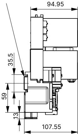
Dimensions in mm, unless otherwise stated.
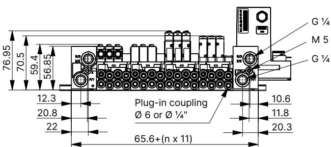
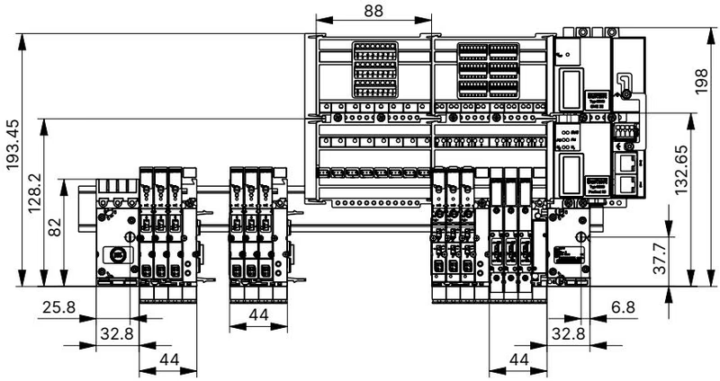
Standard rail EN 50022 35 x 7.5 or 35 x 15:
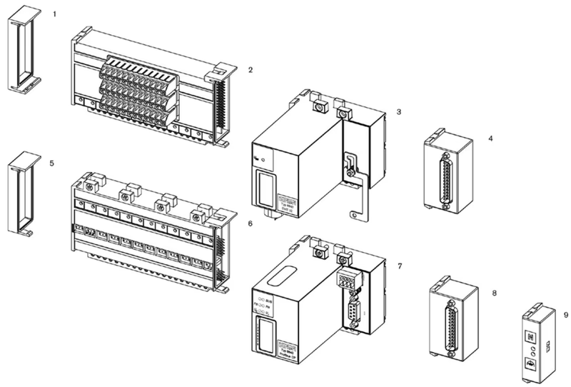
| No. | Element |
|---|---|
| 1 | Electrical end module, left |
| 2 | Terminal module for feedback |
| 3 | Extension module for electrical inputs |
| 4 | Multi-pin digital inputs (initiators) |
| 5 | Electrical end module, left |
| 6 | Basic electrical module standard |
| 7 | Fieldbus module |
| 8 | Multipin valve outputs |
| 9 | Common connection module |
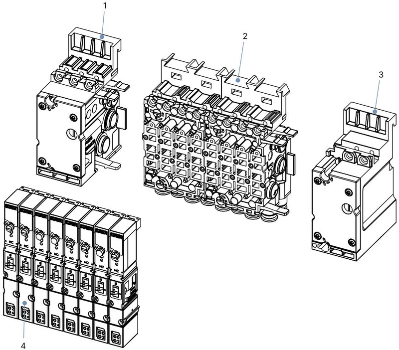
| No. | Element |
|---|---|
| 1 | Pneumatic connection module, left |
| 2 | Basic pneumatic modules |
| 3 | Pneumatic connection module, right |
| 4 | Valves (for example 5/2-way) |
WARNING
Risk of injury due to high pressure and escaping medium. Switch off the pressure before working on the device or system. Vent or drain the pipes.
TIP
Pilot pressure for pneumatic control unit depends on the pressure of the flow medium; it must be between 2 ... 10 bar (at least 70% of operating pressure).
Explore similar products in our catalog


