

PN16

BURKERT Type 8640 modular valve island (SKU 20050149) with 11mm width per station, 4x (2x 3/2) valve function, G 1/4 pressure port, and collective socket module.
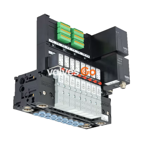
BURKERT Type 8640 modular valve island (SKU 20050149) is designed to solve diverse and complex control problems through its systematic modular construction and combination of pneumatic and electrical interfaces. This REV3 variant features an 11 mm width per station, a 4-bank configuration with 4x (2x 3/2) valve functions, and a collective socket module. Bodies and connection modules are made of high-quality polyamide and are assembled using built-in snap connectors.

| Feature | Specification |
|---|---|
| Valve function | 4x (2x 3/2) valve function C C |
| Add-on dimension | 11 mm |
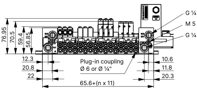
| Pressure port | G 1/4 |
| Working port | D6 |
| Working connection position | Bottom (pneumatic module) |
| Nominal pressure | 2.5 bar to 10 bar |
| Temperature medium | 0 °C to 50 °C |
| Temperature environment | 0 °C to 55 °C |
| Protection type | IP20 |
| Generation | Revision 3 |
| Mounting type | DIN-rail installation |
| Communication interface | Collective socket module |
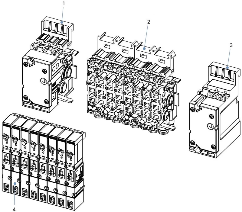
| No. | Element |
|---|---|
| 1 | Pneumatic connection module, left |
| 2 | Basic pneumatic modules |
| 3 | Pneumatic connection module, right |
| 4 | Valves (for example 5/2-way) |
WARNING
Risk of injury due to high pressure and escaping medium. Switch off the pressure before working on the device or system. Vent or drain the pipes.
WARNING
Risk of injury due to electric shock. Switch off voltage before working on the device or system. Secure against reactivation.
TIP
Our push-in connectors meet the requirements specified in the ISO 14743:2020 standard. Ensure that the appropriate combination of hose material (polyamide or polyurethane) and push-in connector is used, as different materials require different holding forces.
Explore similar products in our catalog


