

PN16

BURKERT 20060333 Type 8652 AirLINE is a 16-bank modular valve island with PROFIBUS DPV1, 2x 3/2-way CF-C SIA valves, D10/D6 push-in fittings, pneumatic HotSwap, and ATEX/IECEx Zone 2/22 certification.
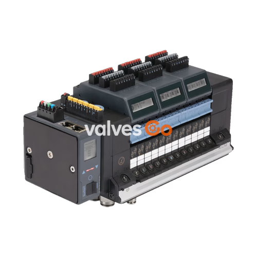
BURKERT 20060333 (Type 8652) AirLINE is a 16-bank modular electro-pneumatic valve island configured for piloting pneumatic actuators and process valves in automation environments. The unit integrates 16 valve slices equipped with 2x 3/2-way CF-C SIA valves, an AirLINE Quick aluminium adapter plate, and a PROFIBUS DPV1 communication module with a 9-pin Sub-D interface. Brass push-in connections provide D10 supply ports and D6 working ports, supported by internal auxiliary pilot air and an intermediate feed supply module.
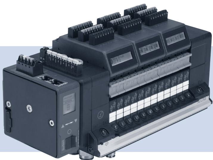
Article 20060333 features 16 operational valve positions, each occupied by a dual 3/2-way normally closed valve slice with safety shut-off (SIA / EVS compatibility). Integrated non-return check valves in exhaust ports 3 (R) and 5 (S) prevent unintentional backpressure build-up across connected pneumatic lines. Port 1 (P) includes an integrated pneumatic HotSwap shut-off element, enabling valve replacement under supply pressure.
| Configuration Parameter | Specification |
|---|---|
| Number of Valve Ports | 16 PCE |
| Valve Positions 1 to 16 | 2x 3/2-way CF-C SIA (32 valve functions total) |
| Pilot Valve Element | Type 6164 (piloting Type 6534 pneumatic valves) |
| Communication Protocol | PROFIBUS DPV1 (modular fieldbus module) |
| Hardware Interface | Sub-D 9-pin |
| Supply Port Connection 1 (P) | Push-in connector D10, brass |
| Working Port Connections 2 (A), 4 (B) | Push-in connector D6, brass |
| Additional Supply Connections | Left, middle, and right push-in D6 and D10 |
| Intermediate Feed Modules | 1 PCE |
| Auxiliary Pilot Air | Internal |
| Base Plate System | AirLINE Quick, aluminium |
| Integrated Non-Return Valves | Ports 3 (R) and 5 (S) |
| Pneumatic HotSwap Check Valve | Port 1 (P) |
| Digital Inputs | None (0 DI modules installed) |
| Parameter | Value |
|---|---|
| Rated Supply Voltage | 24 V DC (±10%) |
| Current Consumption | 3 A |
| Nominal Operating Pressure | -1.00 bar to 10.00 bar |
| Control (Pilot) Pressure | 3.00 bar to 10.00 bar |
| Medium Temperature Range | -10 °C to +55 °C |
| Ambient Temperature Range | -10 °C to +55 °C |
| Degree of Protection | IP20 (individual unit) |
Type 8652 is certified as a component for use in Zone 2 (gas) and Zone 22 (dust) hazardous locations under ATEX Directive 2014/34/EU and the IECEx scheme.
Enclosure and Electrical Protection Limits
Electrical Disconnection and HotSwap in Explosive Atmospheres
Terminals for the 24 V power supply, SIA, EVS, and communication interfaces must only be connected or disconnected when the system is de-energized.
Pneumatic HotSwap functionality must not be used while an explosive atmosphere is present. Valve replacement under pressure is permitted only when test equipment verifies that no hazardous atmosphere exists in the work area.
Type 8652 valve islands certified for hazardous locations carry two nameplates: a general operational nameplate and a dedicated Ex identification plate.
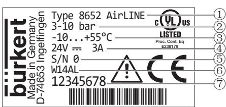
| Position | Description | Example Data |
|---|---|---|
| 1 | Device Type | Type 8652 AirLINE |
| 2 | Pressure Range | 3–10 bar |
| 3 | Ambient Temperature Range | -10 °C to +55 °C |
| 4 | Rated Voltage / Current | 24 V DC / 3 A |
| 5 | Serial Number | S/N 0 |
| 6 | Manufacturing Code | W14AL |
| 7 | Order Article Number | 20060333 (example: 12345678) |
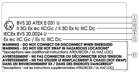
| Position | Parameter | Specification Data |
|---|---|---|
| 1 | Ex Mark | Standard Ex hexagonal logo |
| 2 | ATEX Certificate Number | BVS 20 ATEX E 031 U |
| 3 | ATEX Gas / Dust Marking | II 3G Ex ec IIC Gc / II 3D Ex tc IIIC Dc |
| 4 | IECEx Certificate Number | IECEx BVS 20.0024 U |
| 5 | IECEx Gas / Dust Marking | Ex ec IIC Gc / Ex tc IIIC Dc |
| 6 | Safety Notice | Electrical connection and HotSwap instructions |
| Position | Parameter | Specification Data |
|---|---|---|
| 1 | Zone Gas Marking (US/CA) | Cl I, ZN 2, AEx ec IIC Gc / Ex ec IIC Gc U |
| 2 | Zone Dust Marking (US/CA) | Cl II ZN 22, AEx tc IIIC Dc / Ex tc IIIC Dc U |
| 3 | Division Marking (US/CA) | Cl I, Div 2, Gr A, B, C, D / Cl II, III, Div 2, Gr F, G |
| 4 | ATEX Certificate Number | BVS 20 ATEX E 031 U |
| 5 | Ex Mark | Standard Ex hexagonal logo |
| 6 | ATEX Gas / Dust Marking | II 3G Ex ec IIC Gc / II 3D Ex tc IIIC Dc |
| 7 | IECEx Certificate Number | IECEx BVS 20.0024 U |
| 8 | IECEx Gas / Dust Marking | Ex ec IIC Gc / Ex tc IIIC Dc |
| 9 | Safety Notice | Electrical connection and HotSwap instructions |
Auxiliary Warning Label
If the primary Ex nameplate is obscured by cabinet installation walls, affix the supplied warning adhesive label visibly to the valve island: WARNING DO NOT CONNECT OR DISCONNECT WHEN ENERGIZED.
In hazardous areas, the maximum permissible number of valve functions per valve island is 48. SKU 20060333 provides 16 valve slices of dual 3/2-way valves, totaling 32 valve functions, remaining within the permissible thermal limit for T4 rating.
Explore similar products in our catalog


