

PN16

BURKERT 20062045 Type 8640 modular valve island for pneumatics. Features 11 mm width per station, G 1/4 pressure port, 3/2 valve function, and IP20 protection.
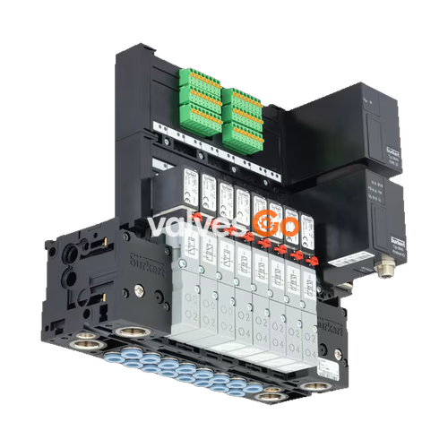
BURKERT 20062045 Type 8640 modular valve island is designed to solve diverse and complex control problems through its systematic modular construction and combination of pneumatic and electrical interfaces. By putting together a row of pneumatic modules, up to 24 valve functionalities can be realized on one valve unit. This specific configuration features an 11 mm width per station, a G 1/4 pressure port, a 3/2 valve function, and IP20 protection due to single wiring.

The following data applies to the 11 mm width per station configuration (compatible with Type 0460, Type 6524, and Type 6525 valves):
| Property | Value |
|---|---|
| Body Material | PA (polyamide), aluminium |
| Seal Material | FKM, NBR and PUR |
| Width per station | 11 mm |
| Number of valve slots | Max. 24 |
| Pressure range | Vac...10 bar (Overpressure to atmospheric pressure) |
| Operating voltage | 24 V DC (±10% voltage tolerance) |
| Operating medium | Oil-free or lubricated compressed dry air, neutral gases (5 μm filter recommended) |
| Compressed air quality | ISO 8573-1: 2010, Class 7.4.4 |
| Air supply connection 1 (P), 3 (R), 5 (S) | G 1/4, D 3/8 |
| Installation position | As required, preferably with actuator upright |
TIP
Pilot pressure for the pneumatic control unit depends on the pressure of the flow medium; it must be between 2 ... 10 bar (at least 70% of operating pressure). Pressure difference between port 1 and 3 must be at least 2 bar.
The 11 mm pneumatics assembly consists of modular components that snap together.
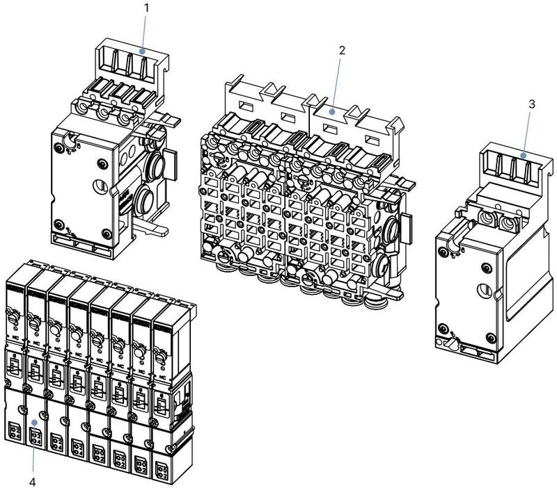
| No. | Element |
|---|---|
| 1 | Pneumatic connection module, left |
| 2 | Basic pneumatic modules |
| 3 | Pneumatic connection module, right |
| 4 | Valves (for example 5/2-way) |
WARNING
Risk of injury due to high pressure and escaping medium. Switch off the pressure before working on the device or system. Vent or drain the pipes.
The valve block can be mounted on a standard rail or directly to a wall.
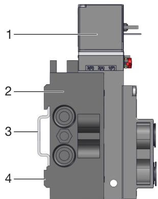
Observe the following tightening torques when screwing into the port connections. The specified tightening torque may vary depending on the sealing system.
| Port size | Marking/function | Recommended tightening torque [Nm] | Maximum tightening torque [Nm] |
|---|---|---|---|
| G 1/4 | P, R/S connection | 4...7 | 20 |
| G 1/8 | P, R/S connection, A/B valve outlets | 3...6 | 7 |
WARNING
Do not use the coil as a lever arm. Do not use a pipe wrench when screwing in.
Explore similar products in our catalog


