

PN16

BURKERT 20062748 Type 8640 is a modular pneumatic valve island featuring 3/2-way mixed valve population, Sub D 25-pin multi-pole interface, D3/8 supply port, and DIN-rail mounting for 2.5 to 10 bar operation.
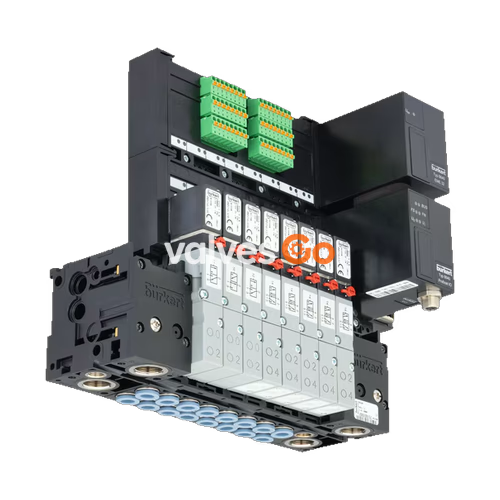
BURKERT 20062748 Type 8640 is a modular pneumatic valve island built with an 11 mm per-station module width and mixed 3/2-way valve functionality. Engineered for controlling neutral gases and filtered compressed air, the island operates within a nominal pressure range of 2.5 to 10.0 bar and an ambient temperature range of 0 °C to +55 °C. The unit integrates a 25-pin Sub-D multi-pole electrical connection with internal Bürkert bus communication, bottom-oriented D1/4 pneumatic working connections, and a D3/8 main supply port. The complete assembly is configured for DIN-rail installation with an IP20 ingress protection rating.
The Type 8640 pneumatic valve island utilizes modular base modules combined with integrated solenoid pilot valves (Type 5470 with Type 6106 pilot stage). The assembly incorporates dedicated pressure supply, exhaust, and working ports arranged along the manifold.
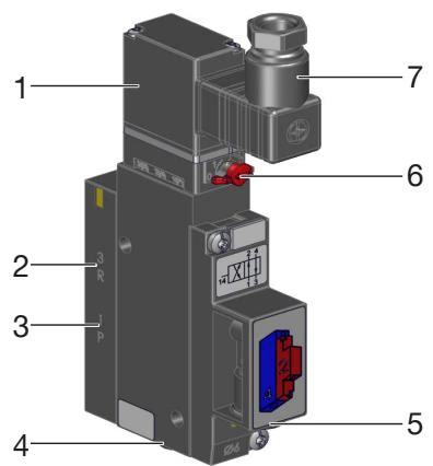
| Item | Designation |
|---|---|
| 1 | Pilot valve Type 6106 |
| 2 | Exhaust port 3 |
| 3 | Pressure port 1 |
| 4 | Working port 4 |
| 5 | Working port 2 |
| 6 | Manual override |
| 7 | Cable plug connection interface |
Ports are identified by molded numbers to ensure correct piping:
Each valve station is equipped with a mechanical manual override for commissioning and testing without electrical actuation.
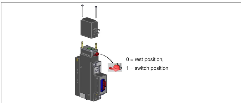
To operate the valve manually, press the manual override down and turn it 90° clockwise until it hits the mechanical stop. In this position, the manual override remains mechanically locked and does not automatically reset. To restore electrical control, rotate the override 90° counter-clockwise back to the neutral position.
Manual Override Safety
Operate the manual override only when the valve station is de-energized. Before placing the system into regular electrical operation, confirm that all manual overrides across the island are rotated back to their zero position.
The 20062748 configuration provides 3/2-way valve operations within the manifold assembly:
| Parameter | Specification Value |
|---|---|
| Type Series | Type 8640 (Generation revision 3) |
| Identification Article Number | 20062748 |
| Station Pitch / Add-on Dimension | 11 mm |
| Operating Pressure Range | 2.5 to 10.0 bar (minimum pressure difference 1 to 3: 2 bar) |
| Pilot Pressure Requirement | 2 to 10 bar (at least 70% of operating pressure) |
| Operating Medium | Filtered compressed air (particle size max. 10 μm), neutral gases (5 μm filtering) |
| Lubrication Condition | Preferably unlubricated; operation with lubricated air is permitted |
| Seal Material | NBR |
| Medium Temperature Range | 0 °C to +50 °C (restricted to dried air below 0 °C) |
| Ambient Temperature Range | 0 °C to +55 °C |
| Storage Temperature Range | -40 °C to +55 °C |
| Electrical Interface Hardware | Sub D 25-pin connector |
| Modular Version / Protocol | Multi-pole control with internal Bürkert bus |
| Degree of Protection | IP20 (overall valve island assembly) |
| Mounting Standard | DIN rail 35 x 15 mm or 35 x 7.5 mm (EN 50022) |
Type 8640 multi-blocks consist of modular interlocking segments mounted between left and right connection modules.
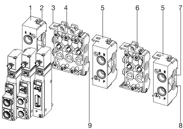
| Item | Designation | Item | Designation |
|---|---|---|---|
| 1 | Left connection module | 6 | Base modules 2-fold |
| 2 | Latch tab | 7 | Exhaust channel 3(R) |
| 3 | Latch hook | 8 | Supply channel 1(P) |
| 4 | Base modules 3-fold | 9 | O-ring seals |
| 5 | Right connection module | — | — |
Seal Integrity
Crushed or misaligned O-rings and profile seals cause pressure loss across pneumatic ducts. Do not pinch seals during module latching.
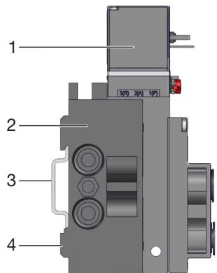
The valve island is factory-configured for DIN-rail mounting and can alternatively be installed directly against a flat mounting surface.
Pneumatic connections must meet dimensional and hardness tolerances to maintain mechanical retention and airtight sealing under pressure.
| Hose Material | Hose Outer Diameter (OD) [mm] | Permitted Deviation [mm] |
|---|---|---|
| Polyamide (PA) | 3 to 10 | ±0.08 |
| Polyamide (PA) | 12 to 16 | ±0.10 |
| Polyurethane (PU) | 3 to 8 | ±0.10 |
| Polyurethane (PU) | 10 to 16 | ±0.15 |
| Hose OD [mm] | 3 | 4 | 6 | 8 | 10 | 12 | 14 | 16 |
|---|---|---|---|---|---|---|---|---|
| Hose OD [in] | 1/8 (3.17) | 5/32 (4.0) | 1/4 (6.35) | 5/16 (8.0) | 3/8 (9.52) | 1/2 (12.7) | — | 5/8 (16.0) |
| Minimum Tensile Force PA [N] | 60 | 70 | 120 | 170 | 250 | 300 | 300 | 350 |
| Minimum Tensile Force PU [N] | 25 | 50 | 100 | 150 | 200 | 200 | 250 | 300 |
Tube Support Sleeves
When using flexible tubing such as polyurethane (PU), support sleeves (ID 20099400) can be inserted inside the hose end to reinforce holding capacity and prevent tube collapse under lateral tension.
Model 20062748 uses a 25-pin Sub-D connector interface to route control signals across the multi-pole block. When individual pilot coils are detached or serviced, ensure proper protective earthing continuity.
| Test Parameter | Test Condition / Value |
|---|---|
| Maximum Protective Earth Resistance | 0.1 Ω |
| Test Voltage | 12 V |
| Test Current | 1 A |
For pulse-driven pilot coils, adhere to polarity markings on the coil surface and maintain a control pulse duration of at least 50 ms.
Electrical Shock Hazard
Disconnect power supplies before disassembling or rewiring modules. Secure electrical systems against accidental reactivation. For external cable plugs (such as Type 2516), tighten mounting screws to 0.3 Nm and verify gasket alignment to maintain enclosure isolation.
| Fault | Possible Cause | Corrective Action |
|---|---|---|
| Valve does not switch | Missing or insufficient supply voltage | Verify power supply and electrical pinout against label specifications. |
| Valve does not switch | Manual override engaged in locked position | Reset manual override 90° counter-clockwise to zero position. |
| Valve does not switch | Inadequate operating pressure | Ensure pressure supply delivers at least 2.0 bar minimum differential pressure. |
| Delayed switching or blow-off at exhaust port | Supply pressure drops during switching | Install larger volume supply lines or buffer reservoirs upstream. |
| Delayed switching or blow-off at exhaust port | Valves energized prior to pneumatic pressurization | Apply pneumatic pressure to the island before triggering electrical switching. |
| Delayed switching or blow-off at exhaust port | Restricted exhaust flow or clogged silencers | Clean contaminated silencers or install higher-flow exhaust units. |
| Delayed switching or blow-off at exhaust port | Contamination inside pilot or main valve seat | Cycle pressure pulses through exhaust ducts or replace the valve insert. |
| External leakage between modules | Pinched, damaged, or missing O-rings | Disassemble block segment, inspect seal grooves, and replace damaged O-rings. |
| Leakage under valve body | Damaged or misaligned base plate gasket | Check valve seating face and re-torque mounting screws to 0.6 Nm. |
The right connection module can be adapted in modular systems to serve as an auxiliary feed point for high-flow installations, or as an intermediate separator to establish distinct pressure stages across a single contiguous block assembly. Internal separating walls at ports 1 and 3 can be opened when continuous through-feeding is required.
Store the valve island in a dry, dust-free enclosure within a temperature range of -40 °C to +55 °C. Retain protective shipping plugs on pneumatic connections and electrical pin covers until mechanical installation. Dispose of decommissioned electronic and pneumatic sub-assemblies through authorized electronic waste (WEEE) collection facilities in compliance with national regulations.
Explore similar products in our catalog


