

PN16

BURKERT 20072611 (Type 5282) servo-assisted 2/2-way diaphragm solenoid valve. Features brass body, G2 internal thread, 24V, FKM seal, and ATEX/IECEx approval.
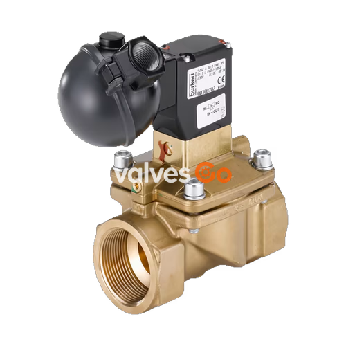
BURKERT 20072611 (Type 5282) is a servo-assisted 2/2-way diaphragm solenoid valve designed to control, shut off, and meter neutral media up to a viscosity of 21 mm²/s. A minimum differential pressure of 0.5 bar is required for the valve to open the full cross-section. The 20072611 model features a brass body with a G2 internal thread, FKM seals for medium temperatures up to 90 °C, and operates on 24 V. It includes ATEX/IECEx explosion protection (Ex mb tb IIIC T130°C Db, Ex eb mb IIC T4 Gb) and provides an IP65 degree of protection when correctly connected.
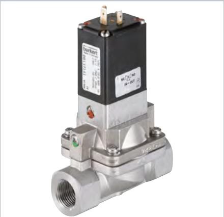
The valve incorporates a separating diaphragm for aggressive and contaminated media, and the closing and opening times can be adjusted individually via side throttle screws. The 3/2-way pilot valve can be converted from NC (Normally Closed) to NO (Normally Open) circuit function by rotating it 180° on the armature.
The 20072611 model operates with Circuit Function A (Normally Closed).
| Symbol | Description |
|---|---|
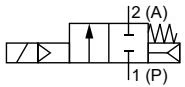 | Circuit function A (CF A) 2/2-way solenoid valve Servo-controlled Normally closed |
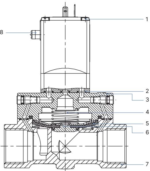
| No. | Element | Material |
|---|---|---|
| 1 | Coil | Epoxy |
| 2 | O-ring | NBR, EPDM, FKM |
| 3 | Cover | Brass (DN 13 stainless steel 1.4408/316, DN 20...DN 50 stainless steel 1.4581/316CB) |
| 4 | Spring | Stainless steel 1.4310/302 |
| 5 | Diaphragm | NBR, EPDM, FKM |
| 6 | Diaphragm holder | Brass, stainless steel 1.4401/316 |
| 7 | Valve body | Brass (DN 13 stainless steel CF3M, DN 20...DN 50 stainless steel 1.4581/316CB) |
| 8 | Manual override | PA |
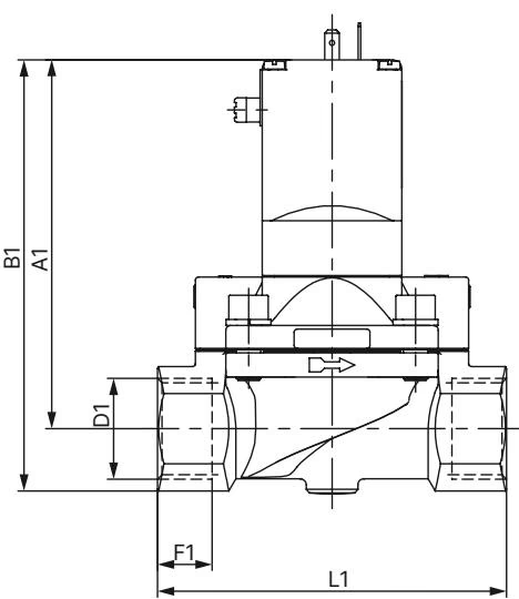
Note: Dimensions in mm. The dimensions D1 and F1 apply to G thread.
| DN | A1 | B1 | G (D1) | G (F1) | E1 | L1 | SW |
|---|---|---|---|---|---|---|---|
| 13 | 109.0 | 123.0 | G 1/2 | 14 | 40 | 65 | 27 |
| 20 | 115.0 | 131.0 | G 3/4 | 16 | 60 | 100 | 32 |
| 25 | 121.5 | 142.0 | G 1 | 18 | 70 | 115 | 41 |
| 32 | 122.0 | 147.0 | G 1 1/4 | 20 | 85 | 126 | 50 |
| 40 | 126.0 | 156.0 | G 1 1/2 | 22 | 85 | 126 | 60 |
| 50 | 142.5 | 177.5 | G 2 | 24 | 115 | 164 | 70 |
| 65 | 142.5 | 185.0 | G 2 1/2 | 27 | 115 | 180 | 85 |
Installation Recommendation
To ensure that the solenoid valve functions reliably, a dirt filter (≤ 500 µm) must be installed in front of the valve inlet.
Breakage Risk
Do not use the coil as a lever arm during installation. Hold the device with a suitable open-end wrench on the body and screw into the pipeline.
When the manual emergency actuation is locked, the valve can no longer be actuated electrically.
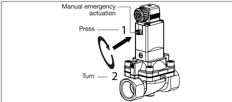
The delivery condition corresponds to the order key. Turning the pilot valve through 180° changes the circuit function of the valve. The circuit function can only be changed for variants up to 10 bar.
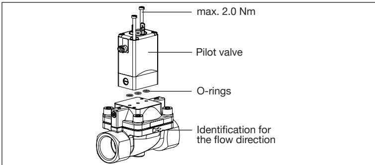
Leakage Hazard
If the O-rings are forgotten or incorrectly inserted during installation of the pilot valve, the device will be damaged and medium will be discharged. Before screwing in the pilot valve, correctly insert O-rings into the depressions.
The closing and opening times of the valve can be changed if required with the side throttle screws.
Pressure Surges
If closing times are fairly short, liquid media cause higher pressure surges. These may reduce the service life of the diaphragm and destroy other devices and components in the system. Discharge of medium occurs if the throttle screws are unscrewed too far.
Explore similar products in our catalog


