


Up to 99.8% Efficiency

BURKERT 20072839 Type 3361 is an electromotive 2-way globe control valve with DN 15 PN25 flange, 24 V DC AG2 1300 N linear actuator, SAFEPOS fail-safe energy pack, stainless steel seat, and integrated digital display.
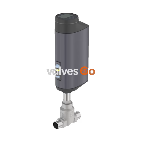
BURKERT 20072839 Type 3361 is an electromotive 2-way globe control valve engineered for demanding process automation and dynamic continuous flow control. Configured under article number 20072839, the assembly combines a cast stainless steel CF3M globe body with an AG2 electromotive linear actuator delivering 1300 N positioning force. Process connection is provided via DN 15 flanges according to DIN EN 1092-1 with a nominal pressure rating of PN 25 (Class 150). The valve trim features an exchangeable stainless steel seat with a 6 mm (1/4") orifice and a linear 25:1 control cone delivering a water flow coefficient Kv of 1.2 m³/h (Cv 1.4 gpm).
Actuation is driven by a 24 V DC brushless motor paired with a precision ball screw, achieving a linear travel speed of 6 mm/s and typical closing times of 3.4 s. The unit includes the integrated SAFEPOS energy-pack emergency electrical storage module, ensuring the valve drives to its safety position (normally opened in factory delivery status) upon power failure. Digital parameterization and local operation are handled through a rugged display module with operating keys, complemented by analogue control inputs and outputs as well as a digital Service-büS communication interface.
| Attribute | Specification Value |
|---|---|
| Article Number | 20072839 |
| Valve Type | Type 3361 (2-way globe control valve) |
| Nominal Diameter | DN 15 (NPS 1/2) |
| Process Connection | Flange DIN EN 1092-1 PN 25 (Class 150) |
| Operating Pressure Range | 0.00 to 25.00 bar(g) |
| Medium Temperature Range | -10 °C to +185 °C |
| Ambient Temperature Range | -25 °C to +65 °C (subject to display/module derating) |
| Seat Diameter | 6 mm (1/4") |
| Flow Capacity | Kv 1.2 m³/h (water) / Cv 1.4 gpm |
| Control Cone Characteristic | Linear 25:1 |
| Flow Direction | Below seat (against closing direction) |
| Valve Seat Seal | Stainless steel 1.4571 (leakage Class IV, DIN EN 60534-4) |
| Body Material | Cast stainless steel CF3M |
| Actuator Size & Thrust | Size AG2 (1300 N nominal driving force) |
| Travel Speed | 6 mm/s |
| Typical Closing Time | 3.4 s (AG2 range: 3.3 to 6.6 s) |
| Supply Voltage | 24 V DC ±10 % (maximum residual ripple 10 %) |
| Current Consumption | AG2 max. 3 A (including 1 A SAFEPOS charging current) |
| Control Function | Normally Opened (NO, delivery status) via energy storage |
| Local Interface | Rugged display module with operation keys |
| Signals & Bus | 1 analogue input, 1 digital input, 1 analogue output, 2 digital outputs, Service-büS |
| Ingress Protection | IP65 / IP67 (DIN EN 60529), NEMA 4X |
| Conformity | Food (EC) 1935/2004 compliant, Ecolab detergent resistant |
Type 3361 actuators are divided into size AG2 (1300 N or 2500 N thrust for seat sizes 3 to 50 mm) and size AG3 (7700 N or 10000 N thrust for seat sizes 40 to 100 mm). Total weight reaches up to 5.5 kg for AG2 and 16 kg for AG3, excluding valve body options. The electric drive maintains zero-power holding tightness against maximum medium pressure in standby conditions, drawing 2 to 5 W.
Position control operates with a dead band of ±0.1 %. The standard duty cycle rating is 100 %. Permissible fluid viscosity spans up to 600 mm²/s across neutral gases, steam, water, alcohols, fuels, hydraulic fluids, salt solutions, and organic solvents. The device can be installed in any orientation, with upright actuator placement preferred.
The wetted materials in article 20072839 comply with Regulation (EC) 1935/2004 according to the manufacturer declaration and meet Ecolab test method F&E/P3-E No. 40-1 for external washdown detergent resistance. Across the broader Type 3361 range, conformity options include:
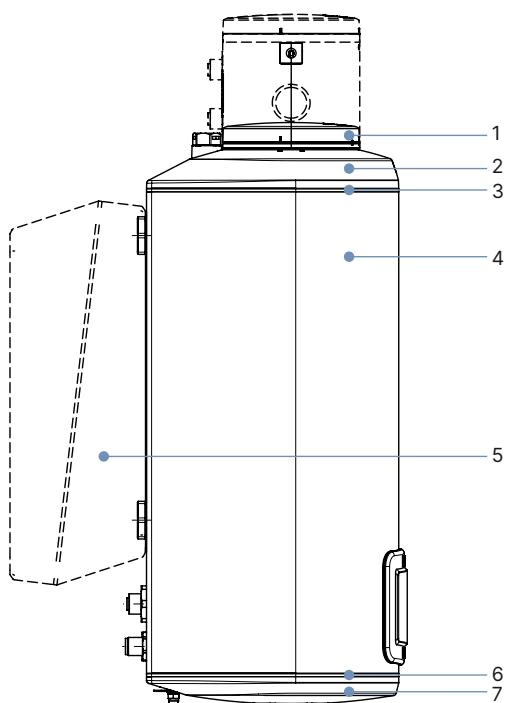
| Item | Component | Standard Material |
|---|---|---|
| 1 | Display housing / blind cover | PPS (standard), stainless steel 1.4301 (ATEX/IECEx) |
| 2 | Actuator cover | PPS |
| 3 | Seal | EPDM |
| 4 | Actuator housing | Powder-coated aluminium |
| 6 | Seal | EPDM |
| 7 | Actuator base | PPS |
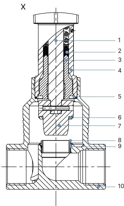
| Item | Component | Material |
|---|---|---|
| 1 | Spindle | Stainless steel 1.4401 (316) / 1.4404 (316L) |
| 2 | Spindle seal | PTFE V-seals (filled) with spring compensation |
| 3 | Spindle guide | Stainless steel 1.4404 (316L) |
| 4 | Packing gland tube | Stainless steel 1.4401 (316) |
| 5 | Seal valve body | Graphite or PTFE |
| 6 | Seat seal | Stainless steel 1.4571 (configured on 20072839), PTFE, or PEEK |
| 7 | Control cone | Stainless steel 1.4571 (optionally hardened) |
| 8 | Valve seat | Stainless steel 1.4571 (optionally hardened) |
| 9 | O-ring valve seat | EPDM or PTFE (seat size ≥ 25 mm) |
| 10 | Valve body | Stainless steel CF3M |
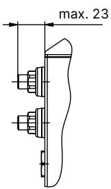
Dimensions in mm. Heights are given for standard variants (H1) and fieldbus gateway variants (H2). The actuator rises approximately 2 mm in the closed position when seating without compression.
| DN | NPS | H1 Standard Variant [mm] | H2 Fieldbus Variant [mm] |
|---|---|---|---|
| 10 | 3/8 | 417 | 489 |
| 15 | 1/2 | 417 | 489 |
| 20 | 3/4 | 423 | 495 |
| 25 | 1 | 446 | 518 |
| 32 | 1 1/4 | 474 | 546 |
| 40 | 1 1/2 | 479 | 551 |
| 50 | 2 | 485 | 557 |
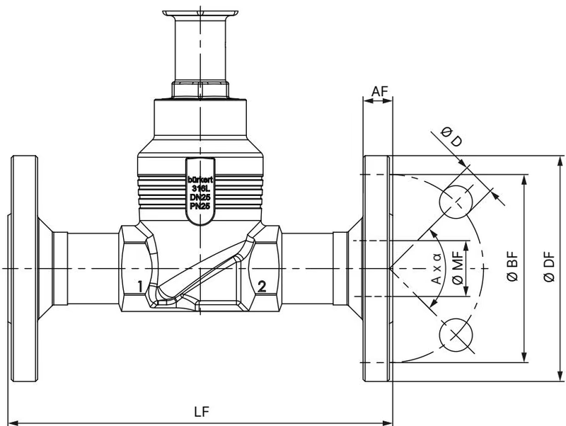
| DN | ∅ DF [mm] | LF [mm] | ∅ BF [mm] | AF [mm] | ∅ D [mm] | Bolt Holes (A x α) | ∅ MF [mm] |
|---|---|---|---|---|---|---|---|
| 10 | 90 | 130 | 60 | 16 | 14 | 4 × 90° | 13.6 |
| 15 | 95 | 130 | 65 | 16 | 14 | 4 × 90° | 18.1 |
| 20 | 105 | 150 | 75 | 18 | 14 | 4 × 90° | 23.7 |
| 25 | 115 | 160 | 85 | 18 | 14 | 4 × 90° | 29.7 |
| 32 | 140 | 180 | 100 | 18 | 18 | 4 × 90° | 38.4 |
| 40 | 150 | 200 | 110 | 18 | 18 | 4 × 90° | 44.3 |
| 50 | 165 | 230 | 125 | 20 | 18 | 4 × 90° | 56.3 |
| 65 | 185 | 290 | 145 | 22 | 18 | 8 × 45° | 66.0 |
| 80 | 200 | 310 | 160 | 24 | 18 | 8 × 45° | 81.0 |
| 100 | 235 | 350 | 190 | 24 | 22 | 8 × 45° | 100.0 |
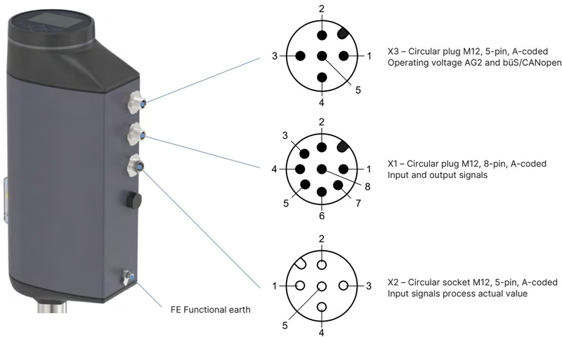
Article 20072839 uses M12 circular connectors on the AG2 actuator base:
| Connector | Pin | Assignment |
|---|---|---|
| X3 (Power & büS) | 1 | CAN Shield / shield |
| M12 plug, 5-pin, A-coded | 2 | Operating voltage 24 V DC ±10 % |
| 3 | GND / CAN_GND | |
| 4 | CAN_H | |
| 5 | CAN_L | |
| X1 (I/O Signals) | 1 | Digital input + |
| M12 plug, 8-pin, A-coded | 2 | GND for digital input and digital outputs |
| 3 | Digital output 2 + (PNP, max. 100 mA) | |
| 4 | Digital output 1 + (PNP, max. 100 mA) | |
| 5 | Analogue output - (0/4..20 mA or 0..5/10 V) | |
| 6 | Analogue output + | |
| 7 | Set-point value / Analogue input - (0/4..20 mA, input impedance 70 Ω; 0..5/10 V, 22 kΩ) | |
| 8 | Set-point value / Analogue input + | |
| X2 (Process Actual) | 1 | Do not connect |
| M12 socket, 5-pin, A-coded | 2 | Do not connect |
| 3 | Do not connect | |
| 4 | Process actual value 4..20 mA (input impedance 80 Ω, 12 bit) | |
| 5 | Process actual value GND |
Type 3361 features an equal-percentage flow characteristic according to DIN EN 60534-2-4 as standard, with linear characteristics available on request. Article 20072839 is configured with a linear 25:1 cone on seat size 6 mm.
Nominal diameter DN 15 (NPS 1/2) with AG2 actuator nominal force 1300 N:
| Seat Size [mm] | Actuator Force [N] | Max Operating Pressure (Seat Leakage) [bar] | Rangeability | Kv at 5% Stroke [m³/h] | Kv at 10% Stroke [m³/h] | Kv at 30% Stroke [m³/h] | Kv at 50% Stroke [m³/h] | Kv at 70% Stroke [m³/h] | Kv at 100% Stroke (Kvs) [m³/h] |
|---|---|---|---|---|---|---|---|---|---|
| 3 | 1300 | 25 (IV) / 40 (IV) | 20:1 | - | 0.005 | 0.013 | 0.026 | 0.044 | 0.1 |
| 3 | 1300 | 25 (IV) / 40 (IV) | 20:1 | - | 0.009 | 0.023 | 0.046 | 0.085 | 0.2 |
| 4 | 1300 | 25 (IV) / 40 (IV) | 30:1 | - | 0.023 | 0.049 | 0.097 | 0.18 | 0.5 |
| 6 (20072839) | 1300 | 25 (IV) | 50:1 | - | 0.007 | 0.045 | 0.16 | 0.41 | 1.25 (linear cone: 1.2) |
| 8 | 1300 | 25 (IV) / 40 (VI) | 50:1 | - | 0.080 | 0.13 | 0.27 | 0.63 | 2.1 |
| 10 | 1300 | 25 (IV) / 40 (VI) | 50:1 | - | 0.11 | 0.19 | 0.49 | 1.1 | 3.1 |
| 15 | 1300 | 25 (IV) / 40 (VI) | 50:1 | 0.14 | 0.17 | 0.35 | 0.80 | 1.8 | 4.3 |
Ambient Temperature Derating
For AG2 actuators fitted with a display module and the SAFEPOS energy-pack, maximum permissible ambient temperature is derated according to medium temperature. At medium temperatures up to +185 °C, ensure ambient conditions do not exceed +55 °C.
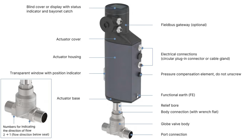
The electromotive linear drive consists of a brushless DC motor, reduction gearing, and a precision spindle system that displaces the control cone. The displacement transducer continuously senses the actual position (POS) of the spindle. The position controller compares this feedback value against the set-point value (CMD). Any control deviation (Xd1) prompts motor actuation via variable CTRL until equilibrium is reached.
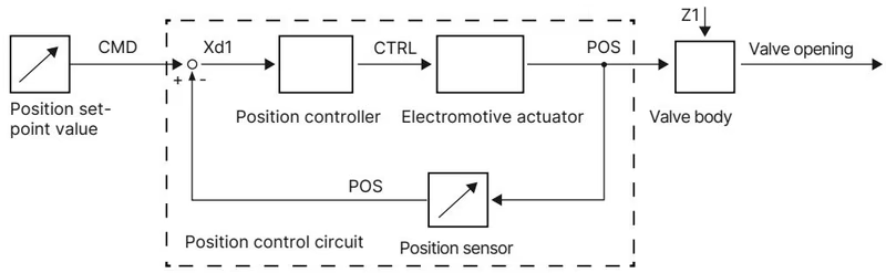
The internal SAFEPOS energy storage module supplies autonomous electrical energy to move the valve into a pre-programmed safety position if operating voltage fails. On article 20072839, the delivery setting is Normally Opened. The internal supercapacitors achieve full operating charge within 120 seconds after supply voltage restoration and provide an operational lifespan up to 10 years with automated state-of-health monitoring.
Mechanical Override Torque Limit
The mechanical manual override must only be actuated when power supply is switched off. Do not exceed the maximum permissible torque of 2 Nm when driving against the end stops, or the internal gearing mechanism will be damaged.
Residual Pressure Hazard
Depressurize and drain or vent pipelines before dismantling the valve or loosening the body connection. Uncontrolled release of pressurized media can cause fatal or severe injuries.
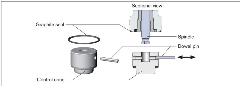
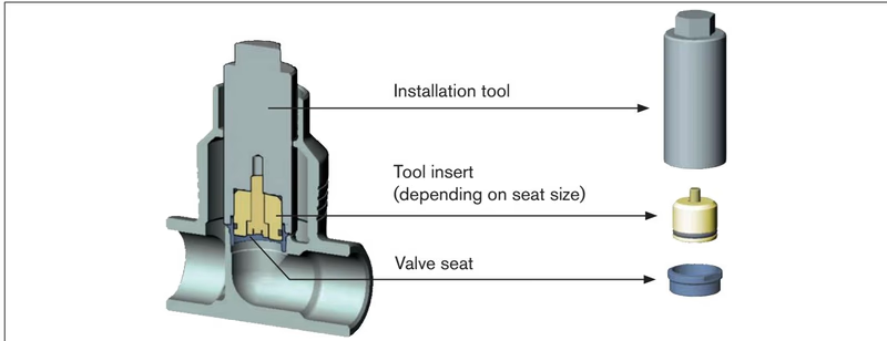
Always fit a new graphite body seal gasket prior to assembly. Lubricate external body connection threads with Klüberpaste UH1 96-402. Thread the actuator onto the body with the valve spindle in the open position. Observe the prescribed tightening torques below.
| Valve Body Connection [DN] | Body Tightening Torque [Nm] | Body Tightening Torque [lbf·ft] |
|---|---|---|
| 10 / 15 | 45 ±3 | 33 ±2 |
| 20 | 50 ±3 | 37 ±2 |
| 25 | 60 ±3 | 44 ±2 |
| 32 / 40 | 65 ±3 | 48 ±2 |
| 50 | 70 ±3 | 52 ±2 |
| 65 | 100 ±3 | 74 ±2 |
| 80 | 120 ±5 | 89 ±2 |
| 100 | 150 ±5 | 111 ±2 |
Running X.TUNE Calibration
After remounting the actuator or replacing internal trim components, run the X.TUNE self-calibration function. The valve must be in an unpressurized pipeline. Never run X.TUNE under medium pressure, as this will distort the stroke limits and cause unstable closed-loop control.
To initiate X.TUNE from the local push buttons, press and hold both OPEN and CLOSE buttons under the cover for 5 seconds until the LED ring illuminates orange. Alternatively, trigger X.TUNE from the display menu under Configuration → Position Controller → Maintenance → Calibration → X.TUNE.
| Item Description | Order / Article No. |
|---|---|
| SAFEPOS energy-pack replacement module (AG2) | 285834 |
| Packing gland seal set (spindle ø10 mm, DN 15/20) | 285685 |
| Stainless steel spindle guide (spindle ø10 mm, DN 15) | 246577 |
| Control cone set DN 15, seat 6 mm, steel/steel (includes dowel pin & graphite seal) | 152696 |
| Valve seat set DN 15, seat 6 mm, stainless steel (includes graphite seal) | 262146 |
| Valve seat installation tool (DN 15 body connection) | 652604 |
| Modified socket wrench SW19 for packing gland (DN 15) | 683220 |
| Body holding device fixture (DN 15 to DN 20) | 693770 |
| M12 circular socket with 5 m cable, 4-pin, A-coded (X3 power supply) | 918038 |
| M12 circular socket with 2 m cable, 8-pin, A-coded (X1 I/O signals) | 919061 |
| M12 circular plug with 2 m cable, 5-pin, shielded (X2 process sensor) | 559177 |
| USB-büS interface set 1 (Type 8923 stick, cables, power supply) | 772426 |
| büS adapter cable (M12 to micro USB service port, length 0.3 m) | 774931 / 773254 |
| Bürkert Communicator PC software (Type 8920) | Type 8920 |
Explore similar products in our catalog


