

PN16

BURKERT 20079750 Type 8640 is a 12-station pneumatic valve block with 5/2-way function H, 16.5 mm station width, G 3/8 pressure supply, D8 bottom push-in working ports, and 2 to 10 bar operating pressure.
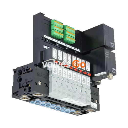
BURKERT 20079750 Type 8640 is a modular pneumatic valve island configured as a 12-station valve block. Designed with a 16.5 mm station pitch, this revision 3 assembly incorporates 12 integrated 5/2-way valve slices (circuit function H), a central G 3/8 supply port, and bottom-facing D8 push-in working connections. The valve block is engineered for direct DIN-rail mounting and operates across a pneumatic pressure range of 2.0 to 10.0 bar, utilizing individual discrete wiring without an internal fieldbus module.
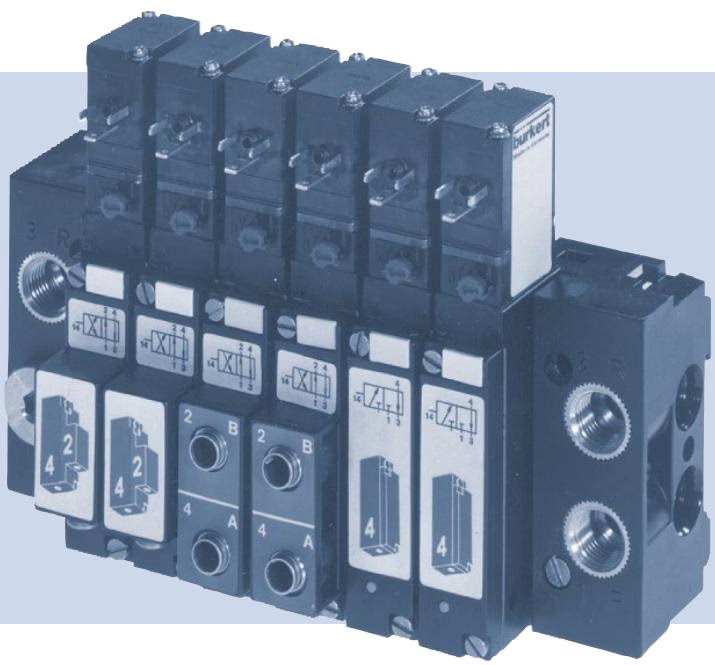
BURKERT 20079750 controls compressed air and neutral gases in industrial automation systems. Compatible media include filtered compressed air with maximum particle size of 10 μm (preferably unlubricated, though lubricated air is permitted) and neutral gases filtered to 5 μm.
Pressure and Electrical Safety
Electrostatic Protection (ESD)
The internal subassemblies contain electrostatic discharge sensitive components. Comply with EN 61340-5-1 handling procedures during installation and avoid touching electrical contact pins under voltage.
The valve block is built on modular pneumatic base modules with snap-in latch mechanisms, carrying individual Type 5470 solenoid valves driven by Type 6106 3/2-way pilot stages.
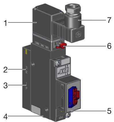
| Item | Designation |
|---|---|
| 1 | Pilot valve Type 6106 |
| 2 | Exhaust port 3 (R) |
| 3 | Pressure port 1 (P) |
| 4 | Working port 4 (A) |
| 5 | Working port 2 (B) |
| 6 | Manual override switch |
| 7 | Cable plug interface (Type 2506 / 2516) |
Pneumatic ports on the valve slices and modules follow standard industrial designations:
| Connection Number | Port Function |
|---|---|
| 1 | Pressure supply port (P) |
| 2 and 4 | Working ports (B and A) |
| 3 | Exhaust port (R) |
| 5 | Secondary exhaust port (S) |
Each valve station includes a mechanical manual override for commissioning and function testing without electrical excitation.
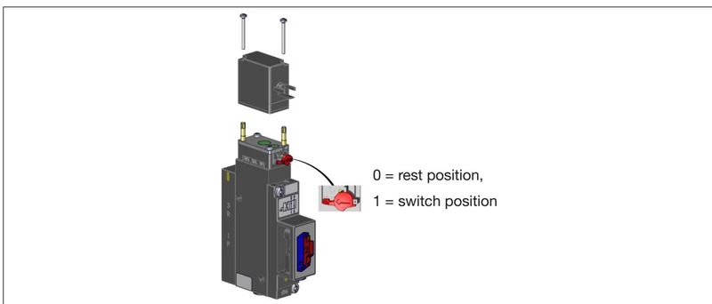
To lock the valve manually, press the manual override actuator and rotate it 90° clockwise until it hits the mechanical stop. The manual override remains mechanically detented and does not spring back automatically. Only actuate the manual override while electrical power is shut off.
Individual valve slices in Type 8640 can be operated in multiple configurations, including function C (3/2-way NC), function D (3/2-way NO), function G (4/2-way), and function H (5/2-way). On 4/2-way configurations, converting to 3/2-way operation is accomplished by sealing one working port with a blanking plug:
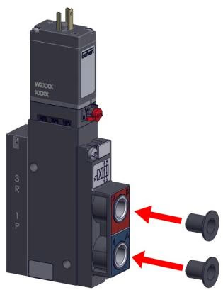
| Working Port 2 | Working Port 4 | Resulting Circuit Function | Rest Position State |
|---|---|---|---|
| Closed (plugged) | Open | C (3/2-way NC) | Port 1 (P) closed, Port 4 (A) exhausted to Port 3 (R) |
| Open | Closed (plugged) | D (3/2-way NO) | Port 1 (P) connected to Port 2 (B), Port 3 (R) closed |
| Specification Parameter | Technical Value |
|---|---|
| Valve Island Type | Type 8640 (Revision 3) |
| Article Number (SKU) | 20079750 |
| Number of Valve Stations | 12 valve slices |
| Valve Function | 12x 5/2-way circuit function H |
| Station Pitch (Width) | 16.5 mm |
| Pneumatic Supply Connection 1 (P) | G 3/8 |
| Pneumatic Working Connections 2 (B) / 4 (A) | D8 push-in fittings (bottom pneumatic module) |
| Operating Pressure Range | 2.0 bar to 10.0 bar |
| Pilot Pressure Requirement | 2.0 to 10.0 bar (at least 70% of line operating pressure) |
| Minimum Pressure Differential (Port 1 to 3) | 2.0 bar |
| Operating Medium | Compressed air (10 μm filtered), neutral gases (5 μm filtered) |
| Sealing Material | NBR |
| Medium Temperature Range | 0 °C to 50 °C (air must be dried below 0 °C) |
| Ambient Temperature Range | 0 °C to 55 °C |
| Integrated Exhaust Check Valves | Included on channels 3 (R) and 5 (S) |
| Pneumatic HotSwap at Port 1 | No |
| Mounting Form | DIN-rail mounting (EN 50022 35x15 or 35x7.5) |
| Control Concept | Single discrete wiring per coil (no bus electronics) |
| Degree of Protection | IP20 |
Functional Reliability During Standstill
If continuous operation is interrupted, BURKERT recommends cycling each valve slice 1 to 2 times daily during idle periods to maintain reliable seat movement and lubrication.
Valves are factory assembled. When orientation requires modification for specific cabinet layouts, the pilot coil can be unfastened and turned 180°:
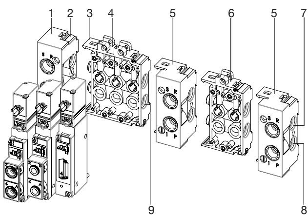
Base modules interlock via lower latch hooks (3) and upper latch tabs (2) joined to the left connection module (1) and right connection module (5):
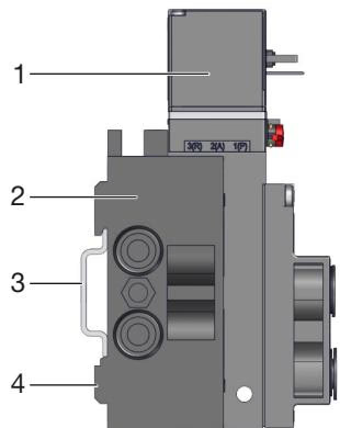
| Item | Component Function |
|---|---|
| 1 | Electrical connector (rotatable by 180°) |
| 2 | Direct wall-mounting screw hole |
| 3 | Standard DIN rail (35 x 15 mm or 35 x 7.5 mm per EN 50022) |
| 4 | Pneumatic connection module |
For DIN-rail mounting, place the upper mounting groove of the valve block over the rail, press the lower clamping blocks into place, and tighten clamping screws. For direct panel mounting, secure the module feet directly to a flat wall surface using M4 fasteners.
| Port Thread Size | Applicable Port Function | Recommended Torque [Nm] | Maximum Torque [Nm] |
|---|---|---|---|
| G 1/4 or NPT 1/4 | Supply port 1 (P), Exhaust 3 (R) / 5 (S) | 4 to 7 | 20 |
| G 1/8 or NPT 1/8 | Working ports 2 (B) / 4 (A), Pilot ports | 3 to 6 | 7 |
Mechanical Stress on Solenoid
Never use the solenoid coil or pilot head as a lever arm when tightening pneumatic threaded fittings.
Pneumatic lines connecting to the bottom D8 push-in fittings must meet the following structural requirements:
| Hose Material | Outer Diameter (OD) [mm] | Permissible OD Deviation [mm] |
|---|---|---|
| Polyamide (PA) | 3 to 10 | ±0.08 |
| Polyamide (PA) | 12 to 16 | ±0.10 |
| Polyurethane (PU) | 3 to 8 | ±0.10 |
| Polyurethane (PU) | 10 to 16 | ±0.15 |
Tubing inserted into push-in claws must withstand standard tensile loads per DIN ISO 14743:2020:
| Metric OD [mm] | Fractional OD [in (mm)] | Minimum Tensile Force PA [N] | Minimum Tensile Force PU [N] |
|---|---|---|---|
| 3 | 1/8 (3.17) | 60 | 25 |
| 4 | 5/32 (4.00) | 70 | 50 |
| 6 | 1/4 (6.35) | 120 | 100 |
| 8 | 5/16 (8.00) | 170 | 150 |
| 10 | 3/8 (9.52) | 250 | 200 |
| 12 | 1/2 (12.70) | 300 | 200 |
| 14 | — | 300 | 250 |
| 16 | 5/8 (16.00) | 350 | 300 |
Tubing Retention with Soft Materials
When using flexible polyurethane (PU) tubing, install internal brass support sleeves (identification part ID 20099400) inside the hose end to preserve circular diameter and guarantee positive seal retention under alternating pressure.
BURKERT 20079750 utilizes discrete single wiring to individual coil sockets. Solenoids interface via standardized cable plugs conforming to DIN EN 175301-803 Form C (such as Type 2516).
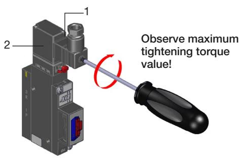
Position the sealing gasket (1) evenly between the coil body and the cable plug (2). Fasten the central fixing screw with a maximum tightening torque of 0.3 Nm. When cable plugs are installed with appropriate seals on all 12 coils, verify continuity across the grounding contacts.
| PE Test Parameter | Permissible Limit | Test Conditions |
|---|---|---|
| Protective conductor resistance | Maximum 0.1 Ω | Test current: 1 A, Test voltage: 12 V |
For impulse (bistable) solenoid versions, electrical control signals require correct polarity and a minimum pulse duration of 50 ms:
| Terminal Configuration | Resulting Pilot State | Port State (Function G) | Port State (Function C) |
|---|---|---|---|
| (+) on pin 2 / (-) on pin 1 | Pilot valve opens | 1 connects to 2, 4 connects to 3 | 1 connects to 4 |
| (+) on pin 1 / (-) on pin 2 | Pilot valve closes | 1 connects to 4, 2 connects to 3 | 4 connects to 3 |
Prior to energizing the valve manifold, perform the following verification steps:
| Fault Condition | Potential Root Cause | Corrective Action |
|---|---|---|
| Valve slices fail to actuate | Missing or insufficient electrical supply voltage | Verify supply wiring; confirm voltage meets nameplate value (tolerance ±10%). |
| Manual override engaged in test lock position | Rotate manual override back to neutral disengaged zero position. | |
| Supply pressure below operating threshold | Restore main pressure to ≥ 2.0 bar; verify upstream regulators and shutoff valves deliver rated volume. | |
| Delayed switching or blow-off at exhaust ports | Main line pressure drops during valve cycling | Install higher capacity supply line or accumulator; ensure pressure remains ≥ 2.0 bar during simultaneous switching. |
| Block pressurized while valves were already energized | Pressurize manifold while solenoid coils remain in de-energized rest state. | |
| Excessive exhaust back-pressure | Clean clogged silencers or enlarge exhaust pipe diameter. | |
| Particulate contamination inside pilot or main spool | Blow out exhaust passages with pulsed air; replace contaminated pilot or valve slice. | |
| Manifold block leakage between slices | Missing, misaligned, or pinched O-rings between modules | Disassemble sub-block, replace defective seals, and verify seating of 2 module O-rings. |
| Damaged flat seal between valve slice and base plate | Inspect valve underside; replace damaged profile seal and retorque to 0.6 Nm. |
The right connection module can serve as an auxiliary feed point for high-flow installations or partition internal supply galleries into independent pressure zones by piercing designated internal isolation walls.
Explore similar products in our catalog


