Type 2032

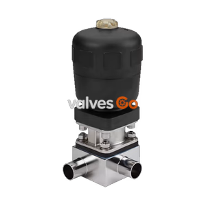
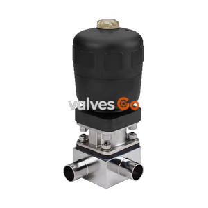
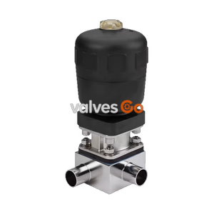
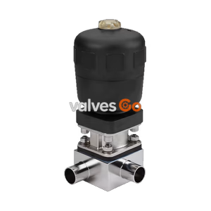
BURKERT Type 2933 2/2-way manual diaphragm valve. Features DN 25 clamp connection, 0-10 bar pressure range, advanced PTFE/EPDM diaphragm, and CIP/SIP capability.
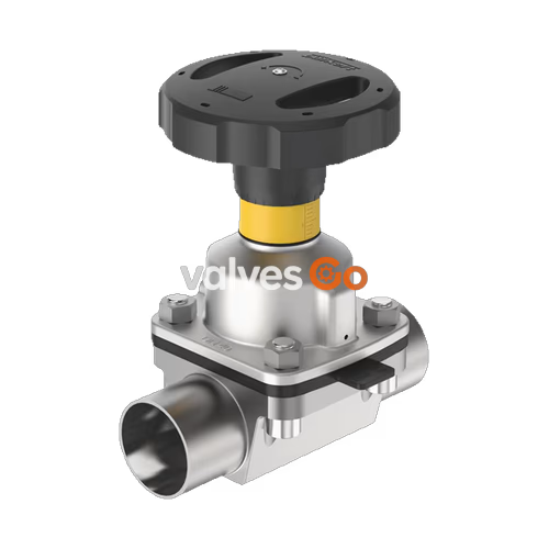
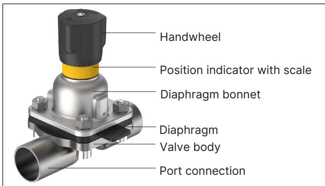
BURKERT Type 2933 manually operated diaphragm valve consists of a manually operated actuator, a diaphragm, and a 2-way valve body. The manual actuator with a plastic or stainless steel handwheel is available with a diaphragm bonnet made of stainless steel or plastic and ensures use in hygienic or aggressive ambient conditions. The flow-optimised valve body with minimum dead space enables high flow values and a wide range of possible applications.
The actuator has a compact, autoclavable design and is compatible with all other Bürkert diaphragm valves. An explosion-proof ATEX/IECEx device variant is available. The manual actuator is equipped with an integrated visual position indicator, a reproducible stroke scale, and an adjustable closing limiter.
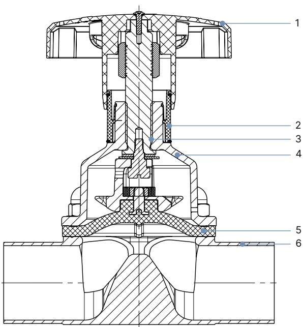
| No. | Element | Material |
|---|---|---|
| 1 | Handwheel | Polyphenylene sulphide (PPS), stainless steel 1.4308 |
| 2 | Visual position indicator | Polyamide (PA), Stainless steel 1.4305 |
| 3 | Valve spindle | Stainless steel 1.4305 |
| 4 | Diaphragm bonnet | Stainless steel 1.4308, polyphenylene sulphide (PPS) |
| 5 | Diaphragm | EPDM (AD), PTFE/EPDM (EA), advanced PTFE/EPDM (EU), laminate of GYLON® and EPDM (ER) |
| 6 | Valve body | Stainless steel tube 1.4435-BN2 / UNS S31603 (316L) |
| Diaphragm size | Maximum permitted medium pressure [bar] (PTFE/advanced PTFE/GYLON®) |
|---|---|
| 8 | 10 |
| 15 | 10 |
| 20 | 10 |
| 25 | 10 |
| 32 | 10 |
| 40 | 10 |
| 50 | 7 / 10 |
WARNING
Pressure data [bar]: Overpressure to atmospheric pressure. Static: When closed, the valve is pressurised on one side with the maximum operating pressure.
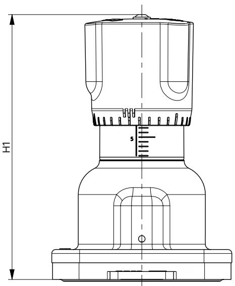
| Diaphragm size | H1 | H2 | ∅ B |
|---|---|---|---|
| 8 | 54 | 49 | 35 |
| 15 | 84 | 78 | 45 |
| 20 | 95 | 86 | 45 |
| 25 | 101 | 90 | 45 |
| 32 | 129 | 115 | 110 |
| 40 | 134 | 116 | 110 |
| 50 | 149 | 125 | 110 |
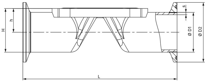
| Diaphragm size | Port connection DN/Inch | ∅D1 | s | ∅D2 | L | h | H |
|---|---|---|---|---|---|---|---|
| ASME BPE | |||||||
| 15 | 3/4" | 19.05 | 1.65 | 25.0 | 102 | 13.20 | 25.73 |
| 20 | 1" | 25.4 | 1.65 | 50.5 | 114 | 16.40 | 41.65 |
| 32 | 1 1/2" | 38.10 | 1.65 | 50.5 | 140 | 22.95 | 48.20 |
| 40 | 2" | 50.80 | 1.65 | 64.0 | 159 | 30.60 | 62.60 |
| 50 | 2 1/2" | 63.5 | 1.65 | 77.5 | 190 | 37.35 | 69.10 |
TIP
It is the responsibility of the installer and the operator to ensure self-draining. The marking on the port connection of the valve body serves as an orientation aid. The marking must point upwards.
| Diaphragm size | Tightening torques [Nm] (VP Body, PTFE/advanced PTFE) |
|---|---|
| 8 | 2.5 |
| 15 | 4 |
| 20 | 4.5 |
| 25 | 8 |
| 32 | 10 |
| 40 | 15 |
| 50 | 20 |
INFO
Tighten each fastening screw in 3 stages (approx. 1/3, approx. 2/3, 3/3 of the tightening torque) crosswise. The diaphragm should be positioned and pressed evenly around the actuator and valve body.
Explore similar products in our catalog