

PN16

BURKERT 20092097 Type 8652 AirLINE is a 4-slot pneumatic valve island with Industrial Ethernet, aluminium AirLINE Quick base, two 5/2-way CF-H valves, integrated check valves, and HotSwap.
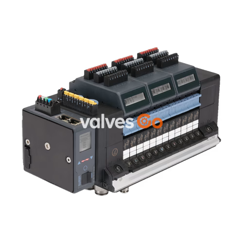
BURKERT 20092097 (Type 8652) is an AirLINE pneumatic valve island configured for process automation environments. Built with a 4-slot base architecture, article 20092097 is factory-equipped with two 5/2-way monostable pilot valves (Circuit Function H) in valve positions 1 and 2, while valve positions 3 and 4 are fitted with blanking plates. Communication is handled by an integrated Industrial Ethernet fieldbus interface supporting PROFINET IO, EtherNet/IP, Modbus TCP, EtherCAT, and CC-Link IE Field Basic via two RJ45 ports. The mechanical connection is established using an anodised aluminium AirLINE Quick adapter plate designed for direct mounting to the floor or wall of a control cabinet, venting exhaust air directly outside the cabinet enclosure.
Type 8652 incorporates integrated check valves in exhaust ducts 3 (R) and 5 (S) to prevent back-pressure peaks from inadvertently switching unactuated process valves. Pneumatic HotSwap technology in supply channel 1 (P) enables valve replacement during active operation under system pressure without process interruption. The illuminated LC display visualises valve switching states, pneumatic supply pressures, device status, and NAMUR NE 107 diagnostic messages in clear text and standardized symbols.
Article 20092097 provides a pre-assembled, fully tested 4-slot valve terminal setup:
| Feature | Specification |
|---|---|
| Article Number (Identcode) | 20092097 |
| Base Valve Island Type | 8652 AirLINE Standard |
| Total Number of Valve Slots | 4 |
| Valve Slot Position 1 | 5/2-way monostable solenoid valve, Circuit Function H (CF-H) |
| Valve Slot Position 2 | 5/2-way monostable solenoid valve, Circuit Function H (CF-H) |
| Valve Slot Position 3 | Blind plate (dummy valve) |
| Valve Slot Position 4 | Blind plate (dummy valve) |
| Adapter Plate Execution | AirLINE Quick, anodised aluminium |
| Compressed Air Supply Connection (Port 1) | Push-in connector D10 mm, nickel-plated brass |
| Working Line Connections (Ports 2 & 4) | Push-in connector D6 mm, nickel-plated brass |
| Auxiliary Pilot Air Supply | Internal feed from main air supply |
| Intermediate Supply Modules | None (0 intermediate feeds) |
| Digital Input (DI) Module | Not fitted (0 digital inputs) |
| Safety Shut-off Variant | Standard 24 V interface plate without SIA shut-off |
| Integrated Check Valves | Fitted in exhaust ducts 3 (R) and 5 (S) |
| Pneumatic HotSwap Function | Integrated in pressure channel 1 (P) |
| Technical Parameter | Value |
|---|---|
| Body Material | Polyamide (PA) |
| Seal Material | NBR and PUR |
| Station Width | 11 mm per valve slice |
| Operating Pressure Range | -1.0 bar to 10.0 bar (vacuum to 10 bar) |
| Auxiliary Pilot Pressure Range | 3.0 bar to 10.0 bar |
| Nominal Flow Rate QNn (Air) | 310 l/min (at +20 °C, 6 bar inlet pressure, 1 bar pressure drop) |
| HotSwap Flow Reduction | Flow reduced by approx. 3% when HotSwap check valve is fitted |
| Operating Medium | Oil-free or lubricated dry compressed air, neutral gases (5 µm filtration recommended) |
| Compressed Air Quality Class | ISO 8573-1:2010, Class 7.4.4 |
| Operating Voltage | 24 V DC (tolerance ±10%) |
| Residual Ripple | 1 Vss |
| Nominal Power per Valve | 0.7 W (drops to 0.175 W after electronic power reduction) |
| Nominal Current per Valve | 29 mA (drops to 10 mA after electronic power reduction) |
| Duty Cycle / Mode of Operation | 100% continuous operation (ED) |
| Switching Time Measurement | Measured according to ISO 12238 standard |
| Ambient Temperature Range | -10 °C to +55 °C |
| Storage Temperature Range | -20 °C to +60 °C |
| Mounting Position | Any orientation |
| Electrical Protection Class | Class III according to DIN EN 61140, VDE 0140 |
| Ingress Protection Rating | IP20 standalone; up to IP65 inside closed control cabinets with AirLINE Quick |
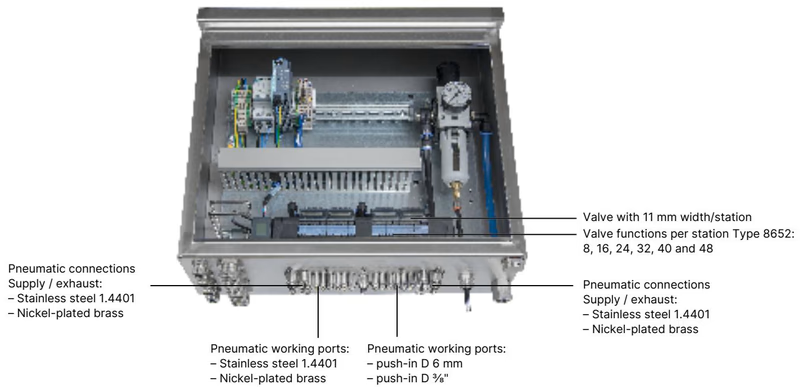
AirLINE Quick allows direct mechanical coupling of Type 8652 to a cutout in the control cabinet floor or wall. Pneumatic supply and exhaust connections, as well as the working lines leading to the field actuators, pass directly through the bottom plate. This configuration eliminates intermediate bulkhead fittings, simplifies internal pneumatic tubing, and prevents exhaust air venting inside the electrical enclosure.
Positions 1 and 2 of article 20092097 utilize Type 6534 pilot valves operating under Circuit Function H (CF-H). Circuit Function H is a servo-assisted 5/2-way valve equipped with a mechanical manual override (latching and spring return).
When pressure is applied to port 1, supply air is directed to either working port 2 or port 4 depending on the electrical actuation state. De-energizing the pilot solenoid returns the spool to its initial rest state via mechanical spring return, venting the active working line through exhaust port 3 or 5.
Flow and Pressure Limits
For vacuum operation or main working pressures below 3 bar, separate auxiliary pilot air at 3 to 10 bar must be supplied to ensure pilot valve actuation. Because 20092097 uses internal pilot air, the main supply pressure on port 1 must be maintained between 3 and 10 bar during normal switching operation.
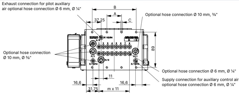
| Terminal Variant | Dimension A [mm] | Dimension B [mm] | Dimension C (Fastening) | m | n |
|---|---|---|---|---|---|
| 4-fold (20092097) | 66 | — | 4 × M5 | 3 | 1 |
| 8-fold | 35 | 111 | 8 × M5 | 7 | 2 |
| 12-fold | 77 | 154 | 10 × M5 | 11 | 3 |
Standard rail installation complies with EN 50022 (35 × 7.5 mm or 35 × 15 mm DIN rails). When using the AirLINE Quick base, the valve terminal attaches using M5 screws.
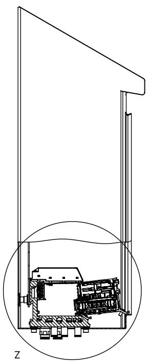
HotSwap Installation Clearance
To enable unhindered removal and replacement of valve slices under pressure using the HotSwap function, maintain the minimum specified clearance between the valve island front surface and the front door or edge of the control cabinet during panel layout.
Type 8652 provides separate electrical connections for electronic communication/display power and pneumatic valve actuation power. Separate circuits allow the pneumatic outputs to be isolated while maintaining continuous fieldbus communication.
Connection is made via a 5-pin spring-loaded terminal block (wire cross-section ≤ 1.5 mm²):
| Terminal | Wire Colour Code | Signal Assignment |
|---|---|---|
| 1 | Red | +24 V DC |
| 2 | White | CAN_H (büS interface) |
| 3 | Green | Shielding |
| 4 | Blue | CAN_L (büS interface) |
| 5 | Black | 0 V DC (GND) |
The 24 V interface plate features a dedicated 2-pin spring-loaded terminal block:
| Terminal Clip | Wire Colour Code | Signal Assignment |
|---|---|---|
| 1 | Red | AUX +24 V DC (Valve Power) |
| 2 | Black | 0 V DC (GND) |
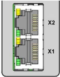
Article 20092097 includes the ME43 Industrial Ethernet gateway module. Two RJ45 connectors (ports X1 and X2) support line and ring topologies for PROFINET IO, EtherNet/IP, Modbus TCP, EtherCAT, and CC-Link IE Field Basic:
| RJ45 Pin | Signal Assignment |
|---|---|
| Pin 1 | TX+ (Transmit Data +) |
| Pin 2 | TX- (Transmit Data -) |
| Pin 3 | RX+ (Receive Data +) |
| Pin 4 | Not connected (N.C.) |
| Pin 5 | Not connected (N.C.) |
| Pin 6 | RX- (Receive Data -) |
| Pin 7 | Not connected (N.C.) |
| Pin 8 | Not connected (N.C.) |
The integrated LC display provides on-device visualization of valve position counters, line pressure status, supply voltage levels, and diagnostic error codes. Diagnostic data conforms to NAMUR NE 107 recommendations, outputting failure, function check, out of specification, and maintenance required indicators.
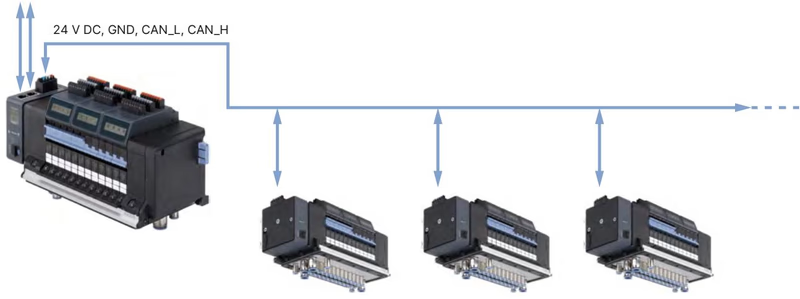
Article 20092097 can act as an Industrial Ethernet master node on an automation network, interconnecting downstream büS-equipped Burkert devices such as Type 8652 slave islands, Type 2012 process control valves, and Type 8697 pneumatic control heads. Device commissioning, parameter assignment, and diagnostic mapping are performed using Bürkert Communicator software (Type 8920) over an EDIP USB-büS interface.
When installed with compatible approved modules, Type 8652 complies with European and international explosion protection standards for Category 3 equipment:
Hazardous Area Operating Conditions
| Component Description | Order Article Number |
|---|---|
| Type 8652 4-Bank Valve Island, 2x CF-H, 2x Blind Plate, Industrial Ethernet (Complete Unit) | 20092097 |
| Type 6534 Solenoid Valve CF-H (5/2-way, 24 V DC, 290 l/min, with screws) | 301376 |
| Blind Plate (Dummy Valve) for unpopulated slots | 335779 |
| Fieldbus Gateway Module Type ME43 (Industrial Ethernet) | 301799 |
| 5-pin Spring-Loaded Terminal Block (Display & Communication Power) | 920180 |
| 2-pin Spring-Loaded Terminal Block (Pneumatic Valve AUX Power) | 920442 |
| Fastening Screw Set M5 × 10 A2 DIN 6912 (10 pieces) | 308661 |
| Height Adapter for 4-fold Base without intermediate feed | 60031491 |
| Retaining Plate for 4-fold Base (cabinet exterior) | 60005571 |
| USB büS Interface Set 1 (Type 8923) for Bürkert Communicator | 772426 |
Explore similar products in our catalog


