

PN16

BURKERT 20093842 Type 6281 is a servo-assisted 2/2-way normally closed diaphragm solenoid valve with brass body, EPDM seal, G 3/4 ports, 0.2-16 bar operating pressure, and 24 V AC 50/60 Hz coil.
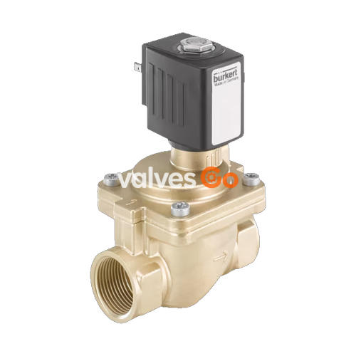
BURKERT 20093842 Type 6281 is a servo-assisted 2/2-way diaphragm solenoid valve designed for controlling, shutting off, and dosing neutral liquid and gaseous media with a viscosity up to 21 mm²/s. Built as a complete valve assembly in generation EV, it features a DN 20 (3/4 inch) main orifice, internal G 3/4 thread connections, a brass body meeting DIN EN 50930-6 drinking water standards, and EPDM seals certified under the French ACS drinking water standard. The valve operates in normally closed circuit function A, driven by a 24 V AC (50/60 Hz) central screwed coil assembly that delivers vibration-resistant operation and damped, quiet closing.
With an operating differential pressure requirement between 0.2 bar and 16 bar, the valve reaches a water flow factor Kv of 8.5 m³/h and a gas flow rate QNn of 9,100 l/min. The electrical interface conforms to DIN EN 175301-803 Form A, achieving IP65 ingress protection when fitted with a suitable cable plug such as Bürkert Type 2518 or Type 2509. Rated for 100% ED continuous operation across a medium temperature span of -30 °C to +90 °C, the unit is intended for water supply systems, industrial process circuits, and general automation equipment.
BURKERT 20093842 operates according to Circuit Function A (CF A). In the de-energized rest state, the valve is closed by spring force and medium pressure acting above the diaphragm. When the solenoid is energized, the plunger opens the 1.3 mm pilot control bore, venting the pressure chamber above the diaphragm toward the valve outlet. Upstream pressure below the diaphragm then lifts the main seal from the seat, establishing flow above the seat.
Minimum Operating Pressure Requirement
Type 6281 is a servo-assisted valve requiring a minimum differential pressure of 0.2 bar between inlet and outlet to function. A differential pressure of 0.5 bar is required to fully open the complete cross-section.
Switching performance measured at +20 °C and 6 bar inlet pressure yields an opening time of 0.1 to 1.5 seconds (pressure drop to 90% of differential flow pressure) and a closing time of 0.2 to 4.0 seconds (pressure build-up to 90% of inlet pressure).
| Parameter | Value |
|---|---|
| Valve Type | 6281 (Generation EV) |
| Article Number | 20093842 |
| Circuit Function | Circuit function A (2/2-way, NC) |
| Fluidic Connection Number | 2 ports, 2 switching positions |
| Port Connection 1 & 2 | Internal thread G 3/4 (marking 3/4) |
| Main Valve Orifice (DN) | 20 mm (3/4 inch) |
| Pilot Control Orifice | 1.3 mm |
| Flow Direction | Above seat |
| Nominal Pressure Rating | PN 16 (DIN EN 1333) |
| Operating Pressure Range | 0.2 bar to 16 bar |
| Flow Coefficient Kv (Water) | 8.5 m³/h (measured at +20 °C, 1 bar Δp) |
| Nominal Flow Rate QNn (Gas) | 9,100 l/min |
| Wetted Body Material | Brass acc. to DIN EN 50930-6 |
| Seat & Outer Seal Material | EPDM (Ethylene-propylene-diene rubber) |
| Medium Temperature Range | -30 °C to +90 °C |
| Max. Ambient Temperature | +55 °C |
| Actuator Type | Plunger valve (solenoid width 32 mm, AC10) |
| Operating Voltage | 24 V AC (50/60 Hz, AC only) |
| Voltage Tolerance | ±10% |
| Duty Cycle | 100% ED continuous operation |
| Coil Insulation Class | Class B (polyamide) |
| Protection Class | IP65 (with cable plug connected) |
| Installation Length | 80 mm |
| Certifications | ACS (Material-approval-drinking water), CE, EAC |
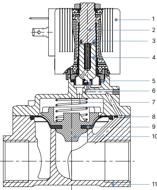
| No. | Element | Material |
|---|---|---|
| 1 | Solenoid coil | Polyamide (Class B) |
| 2 | Stopper | Stainless steel 1.4113 |
| 3 | Shading ring | Copper (Cu, brass version) |
| 4 | Magnetic core (plunger) | Stainless steel 1.4113 |
| 5 | O-ring | EPDM |
| 6 | Core seal | EPDM |
| 7 | Core spring | Stainless steel 1.4310 |
| 8 | O-ring | EPDM |
| 9 | Diaphragm | EPDM |
| 10 | Diaphragm holder | PPS GF40 |
| 11 | Valve body | Brass acc. to DIN EN 50930-6 |
Permissible media for the EPDM seal combination comprise cold and hot water, as well as oil-free and fat-free liquids. Chemical compatibility can be verified through the Bürkert resistApp platform.
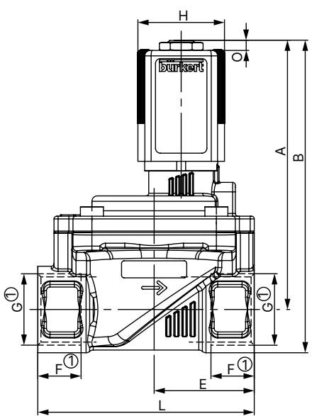
| Dimension Parameter | Value (mm) | Description |
|---|---|---|
| Orifice (DN) | 20 | Main flow diameter |
| Port Thread (G) | G 3/4 | Thread marking G1 |
| Thread Engagement Depth (F1) | 16 | Female thread depth |
| Total Body Length (L) | 80 | Face-to-face installation length |
| Width Across Flats (SW) | 32 | Wrench flat dimension on ports |
| Valve Body Width (E) | 37 | Body center-to-side dimension |
| Center Height to Coil Top (A) | 99.6 | Height from pipe centerline to coil top |
| Total Height to Plug Top (B) | 115.6 | Height from pipe centerline including cable plug |
| Coil Assembly Width (C) | 60 | Solenoid operator profile width |
| Coil Length with Plug (D) | 74 | Clearance required for electrical connector |
| Base Mounting Offset (N) | 10 | Bottom clearance dimension |
| Solenoid Coil Width (H) | 32 | AC10 coil size 5 |
BURKERT 20093842 is equipped with an AC10 size coil (32 mm width) operating at 24 V AC 50/60 Hz. The coil system provides power consumption values defined in standard operation:
| Operating Parameter | Specification |
|---|---|
| Operating Voltage | 24 V AC (50/60 Hz) |
| Voltage Tolerance | ±10% |
| Inrush Power (AC) | 24 VA |
| Holding Power (AC) | 14 VA / 8 W (nominal 16 VA / 7 W) |
| Electrical Connection Type | Cable plug Form A acc. to DIN EN 175301-803 |
| Recommended Cable Plug | Bürkert Type 2518 or Type 2509 (ordered separately) |
| Cable Plug Tightening Torque | Max. 1.0 Nm |
Prior to installing the valve into the pipework, purge and clean all pipelines to remove welding residues, swarf, and dirt. A dirt trap (strainer mesh ≤ 500 µm) should be placed upstream of the valve inlet.
Installation Position & Flow Direction
Pressure and Voltage Hazard
During mechanical piping installation, hold the valve body firmly using an open-end wrench across the wrench flats (SW 32). Do not use the solenoid coil as a lever arm. Tighten female pipe connections securely without introducing mechanical bending stress to the valve housing.
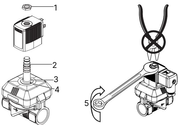
Solenoid Coil Mounting Precautions
In continuous operation, functional reliability is maintained by periodic cycling. For systems subject to extended downtime, executing at least 1 to 2 switching operations daily is recommended.
| Symptom | Probable Cause | Corrective Action |
|---|---|---|
| Valve does not actuate | Electrical interruption or coil short circuit | Check power supply, voltage, and coil resistance |
| Valve does not actuate | Core area contaminated or seized | Clean core guide tube, plunger, and armature area |
| Valve does not actuate | Operating pressure out of bounds | Verify supply pressure is within 0.2 to 16 bar range |
| Valve does not close | Valve interior or pilot channel blocked | Clean body interior; clear pilot bore in diaphragm |
| Valve does not close | Diaphragm defective or degraded | Replace diaphragm and seal assembly |
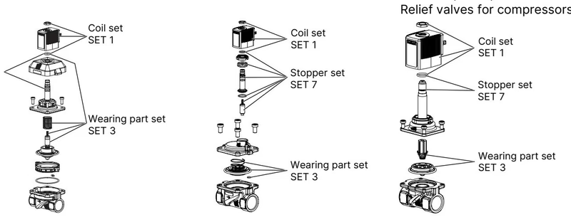
Original factory spare parts are ordered by referencing device article number 20093842 and the required set code:
Electrical cable plugs must be ordered separately. Compatible Type 2518 and Type 2509 connectors complying with DIN EN 175301-803 Form A include:
| Accessory Description | Operating Voltage | Article No. |
|---|---|---|
| Type 2518 Cable Plug without wiring | 0–250 V AC/DC | 314802 |
| Type 2518 Cable Plug with LED indicator | 12–24 V AC/DC | 314812 |
| Type 2518 Cable Plug with LED and varistor | 12–24 V AC/DC | 314820 |
| Type 2518 Cable Plug with rectifier, LED, and varistor | 12–24 V AC/DC | 314816 |
| Type 2509 Cable Plug standard without wiring | 0–250 V AC/DC | 137943 |
| Article No. | Circuit Function | Seal Material | Voltage / Frequency | Pressure Range | Kv (Water) |
|---|---|---|---|---|---|
| 20093842 | A (NC) | EPDM | 24 V AC (50/60 Hz) | 0.2–16 bar | 8.5 m³/h |
| 221905 | A (NC) | EPDM | 24 V AC (50/60 Hz) | 0.2–16 bar | 8.5 m³/h |
| 221904 | A (NC) | EPDM | 24 V DC | 0.2–16 bar | 8.5 m³/h |
| 221906 | A (NC) | EPDM | 230 V AC (50/60 Hz) | 0.2–16 bar | 8.5 m³/h |
| 221851 | A (NC) | NBR | 24 V AC (50/60 Hz) | 0.2–16 bar | 8.5 m³/h |
| 221850 | A (NC) | NBR | 24 V DC | 0.2–16 bar | 8.5 m³/h |
| 221852 | A (NC) | NBR | 230 V AC (50/60 Hz) | 0.2–16 bar | 8.5 m³/h |
Explore similar products in our catalog


