Up to 99.8% Efficiency

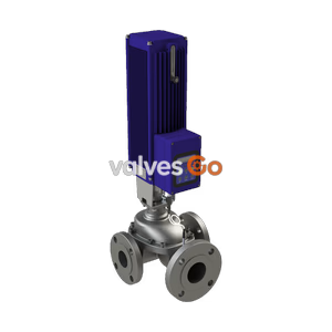
BURKERT 20093966 (Type 3361) is a 24 V DC electromotive globe control valve with DN 25 welded ports, hardened stainless steel trim, 12 m3/h Kvs, integrated positioner, display, and SAFEPOS fail-safe energy pack.
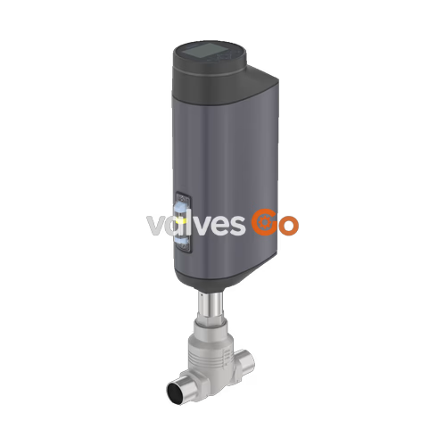
BURKERT 20093966 (Type 3361) is an electromotive 2-way globe control valve engineered for demanding continuous control tasks in process automation. Driven by a brushless DC motor with an integrated ball screw linear actuator, the unit achieves a positioning linear speed of 6 mm/s with a position deadband of ±0.1%. This configuration features port size DN 25 with welded pipe ends according to DIN EN ISO 1127 / ISO 4200 / DIN 11866 Series B, a hardened stainless steel seat and cone set (orifice size 25 mm) delivering a rated Kvs value of 12 m³/h, an equal percentage 50:1 flow characteristic, and an operating pressure range of 0 to 25 bar(g).
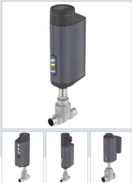
Article 20093966 is delivered in a normally closed fail-safe configuration powered by the integrated SAFEPOS energy-pack. It operates on a 24 V DC power supply, includes an integrated positioner with an illuminated display module, provides multi-signal analog and digital input/output connections, and has undergone specific testing for oxygen service compatibility up to 25 bar(g) at temperatures between -10 °C and +60 °C.
| Parameter | Specification Details |
|---|---|
| Article Number (MPN) | 20093966 |
| Type | 3361 |
| Valve Construction | 2-way globe control valve (flow below seat, 2 → 1) |
| Pipe Connection | Welded spigot: DIN EN ISO 1127 / ISO 4200 / DIN 11866 Series B |
| Port Connection Size | DN 25 (NPS 1), tube dimensions 33.7 x 2.0 mm |
| Valve Seat Diameter | 25 mm (Seat size 25) |
| Nominal Pressure Class | PN 25 (DIN EN 1333), Class 150 (DIN EN 1759) |
| Operating Pressure Range | 0 to 25 bar(g) |
| Rated Flow Coefficient | Kvs 12 m³/h (Cv 14 gpm) |
| Theoretical Control Ratio | 50:1 (equal percentage curve) |
| Seat Leakage Class | Class IV according to DIN EN 60534-4 (metal-to-metal hardened seat) |
| Actuator Size & Thrust | AG2 (1,300 N driving force) |
| Positioning Speed | 6 mm/s |
| Control Deadband | ±0.1% |
| Closing Time | 3.3 to 6.6 s (typical 3.3 s depending on operating conditions) |
| Supply Voltage | 24 V DC ±10% (maximum residual ripple 10%) |
| Current Consumption | Max. 3 A (at max. load, including 1 A charging current for SAFEPOS energy-pack) |
| Standby Power | 2 to 5 W |
| Medium Temperature Range | -10 °C to +60 °C (oxygen version rating) |
| Ambient Temperature Range | -25 °C to +55 °C |
| Fluid Viscosity Limit | Up to 600 mm²/s |
| Ingress Protection Rating | IP65 / IP67 (DIN EN 60529), NEMA 4X |
| Protection Class | Class III (DIN EN 61140) |
| Duty Cycle | 100% continuous |
The wetted section and electromotive drive housing use corrosion-resistant materials suitable for clean industrial processes and aggressive environmental conditions.
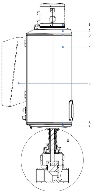
| Item | Component | Material |
|---|---|---|
| 1 | Display housing / blind cover | PPS (polyphenylene sulphide) |
| 2 | Actuator cover | PPS |
| 3 | Actuator cover seals | EPDM |
| 4 | Actuator housing | Powder-coated aluminium |
| 6 | Housing seal | EPDM |
| 7 | Actuator base | PPS |
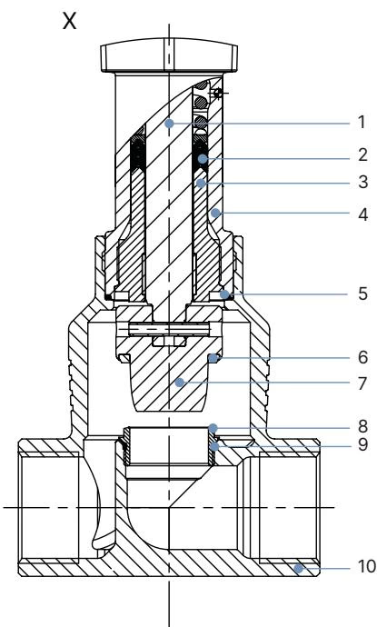
| Item | Component | Material Specification |
|---|---|---|
| 1 | Valve spindle | Stainless steel 1.4401 (316) / 1.4404 (316L) |
| 2 | Spindle sealing gland | Self-adjusting solid PTFE V-rings with spring compensation |
| 3 | Spindle guide | Stainless steel 1.4404 (316L) |
| 4 | Packing gland tube | Stainless steel 1.4401 (316) |
| 5 | Body seal ring | Graphite or PTFE |
| 6 | Seat seal | Hardened stainless steel 1.4571 (metallic seal) |
| 7 | Control cone | Hardened stainless steel 1.4571 |
| 8 | Screw-in valve seat | Hardened stainless steel 1.4571 |
| 9 | Seat O-ring | EPDM or PTFE |
| 10 | Valve body | Cast stainless steel CF3M |
Type 3361 DN 25 with welded spigots complies with standardized tube line dimensions. Actuator height H1 indicates standard configuration without fieldbus gateway module.
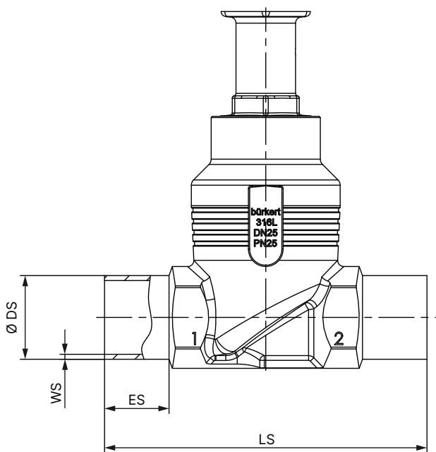
| Nominal Port DN | Pipe OD ∅ DS [mm] | Wall Thickness WS [mm] | Port Length LS [mm] | Spigot Length ES [mm] | Standard Height H1 [mm] |
|---|---|---|---|---|---|
| DN 10 | 17.2 | 1.6 | 90 | 20 | 417 |
| DN 15 | 21.3 | 1.6 | 90 | 20 | 417 |
| DN 20 | 26.9 | 1.6 | 100 | 20 | 423 |
| DN 25 | 33.7 | 2.0 | 130 | 26 | 446 |
| DN 32 | 42.4 | 2.0 | 140 | 26 | 474 |
| DN 40 | 48.3 | 2.0 | 150 | 26 | 479 |
| DN 50 | 60.3 | 2.0 | 175 | 26 | 485 |
Actuator Dimensions in Closed State
In the fully seated closed position without tight-closing function enabled, the actuator height extends upward by approximately 2 mm.
The equal percentage flow characteristic curve conforms to DIN EN 60534-2-4 with a theoretical control ratio of 50:1. Medium flow must be directed below the seat (from port 2 to port 1).
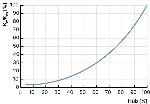
| Stroke [%] | Kv Value [m³/h] | Stroke [%] | Kv Value [m³/h] |
|---|---|---|---|
| 5% | 0.35 | 60% | 3.4 |
| 10% | 0.38 | 70% | 5.1 |
| 20% | 0.65 | 80% | 7.0 |
| 30% | 1.0 | 90% | 9.4 |
| 40% | 1.5 | 100% (Kvs) | 12.0 |
| 50% | 2.2 | Theoretical Control Ratio | 50:1 |
Hardened stainless steel trims (seat and cone) resist mechanical erosion, cavitation, and abrasive media, providing extended service intervals under rigorous process conditions. Seat leakage conforms to DIN EN 60534-4 Class IV (permissible leakage rate 0.01% of nominal flow capacity).
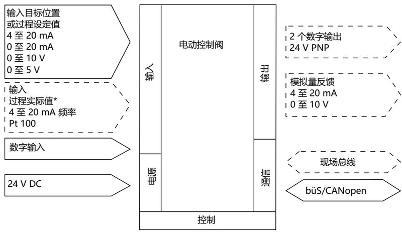
Electrical connections are routed via industrial M12 circular connectors. The valve operates with standard analog setpoints while supplying active process status feedback.
| Pin | Signal Assignment |
|---|---|
| 1 | Digital input + |
| 2 | GND for digital input and digital outputs |
| 3 | Digital output 2 + |
| 4 | Digital output 1 + |
| 5 | Analogue output - |
| 6 | Analogue output + |
| 7 | Setpoint / analogue input - |
| 8 | Setpoint / analogue input + |
| Pin | Signal Assignment |
|---|---|
| 1 | CAN shield |
| 2 | Operating voltage 24 V DC ±10% |
| 3 | GND / CAN_GND |
| 4 | CAN_H |
| 5 | CAN_L |
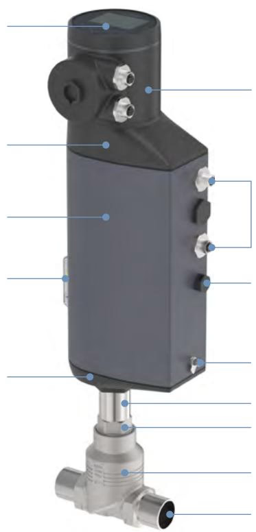
Type 3361 AG2 features a hygienic, enclosed aluminium and high-performance polymer housing with IP65/IP67 rating and vibration resistance.
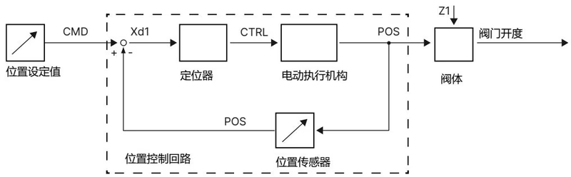
The internal non-contact displacement sensor monitors actual linear position (POS). The digital positioner compares this value against the external setpoint (CMD). If an error deviation (Xd1) occurs, the controller drives the motor with variable CTRL until the setpoint position is reached with a deadband precision of ±0.1%.
Fail-Safe Return Function (SAFEPOS Energy-Pack)
Article 20093966 includes an internal SAFEPOS energy-pack storage module. In the event of an external 24 V DC power failure, the energy pack delivers stored power to move the valve to its programmed safety position (factory preset to fully closed). Charging time to full readiness is 120 seconds or less after power restoration.
Operating Limits & Medium Compatibility
Routine maintenance of the control valve is supported by modular replacement assemblies, including screw-in valve seats and replaceable packing glands.
| Connection Point | Tool / Method | Specified Torque |
|---|---|---|
| Valve Body Connection | Open-end wrench on flats | 60 ± 3 Nm |
| Valve Seat (Seat size 25) | Installation tool (Order No. 652606) | 40 + 5 Nm |
| Spindle Guide (Packing gland) | Modified socket wrench SW21 (Order No. 683223) | 25 Nm |
| Actuator Housing Fastening Screws | Torx T25 | 5 Nm |
| Display / Gateway Fastening Screws | Torx T20 / 3 mm Hex key | 1.1 Nm |
| Mechanical Manual Override | 3 mm Allen key | Max. 2 Nm |
When replacing the control cone, the dowel pin on the 14 mm diameter spindle (DN 25 to 50) must be removed and driven in using a 5 mm pin punch while supporting the cylindrical section in a prism fixture. Do not scratch or indent the profiled control surface.
Position Controller Calibration (X.TUNE)
After remounting the actuator or replacing internal trim components, the X.TUNE self-calibration routine must be executed to recalibrate mechanical stroke limits:
CONFIGURATION → Position controller → MAINTENANCE → CALIBRATION → X.TUNE.Explore similar products in our catalog