Type 2032

BURKERT 20099135 (Type 2933) is a manually operated 2/2-way diaphragm valve with DN 40 welded connection, investment-cast 316L body, PPS handwheel, and EPDM seal rated for 0-10 bar and -10 °C to 143 °C.
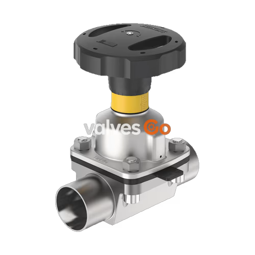
BURKERT 20099135 (Type 2933) is a manually operated 2/2-way shut-off diaphragm valve designed for hygienic, sterile, and aggressive fluid service. The unit pairs an investment-cast stainless steel 316L (1.4435) valve body with a high-temperature EPDM diaphragm and a compact, autoclavable polyphenylene sulphide (PPS) actuator. Configured with DN 40 (NPS 1 1/2, 38.1 x 1.65 mm) butt-weld ends matching ASME BPE and DIN 11866 Series C standards, it delivers a water flow coefficient of Kv 35 m³/h (Cv 40.8 gpm) across an operating pressure range of 0 to 10 bar.
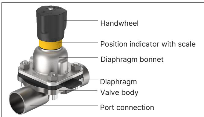
Equipped with a 110 mm diameter handwheel (size M), an integrated visual position indicator, and an adjustable internal closing limiter, BURKERT 20099135 protects elastomeric seating surfaces from excessive manual clamping forces. The valve is fully clean-in-place (CIP) and steam-in-place (SIP) capable, meeting strict sanitary criteria including USP Class VI, FDA 21 CFR, and EC 1935/2004 compliance.
| Technical Parameter | Specification |
|---|---|
| Product Identification | Article no. 20099135, Type 2933, Data matrix code |
| Operating Function | 2/2-way manual shut-off valve |
| Port Connection Size | DN 40 (NPS 1 1/2) - 38.1 x 1.65 mm |
| Connection Standard | ASME BPE / DIN 11866 Series C / BS 4825 |
| Port Connection Type | Welded connection (ASME BPE SODH) |
| Valve Body Material | Investment-cast stainless steel 316L / 1.4435 (VG) |
| Diaphragm Bonnet Material | PPS (polyphenylene sulphide) |
| Manual Override / Handwheel | PPS (polyphenylene sulphide), diameter 110 mm |
| Diaphragm Material | EPDM high-temperature (AD) |
| Diaphragm Size | Size 40 (threaded pin connection) |
| Flow Coefficient | Kv 35 m³/h (Cv 40.8 gal/min, water) |
| Operating Medium Pressure | 0 to 10 bar (PN 10 / Class 150) |
| Medium Temperature | -10 °C to +143 °C (steam sterilisation to +150 °C for 60 min) |
| Ambient Temperature | -10 °C to +130 °C (short-term up to +150 °C), autoclavable |
| Sanitary Compliance | USP Class VI, FDA compliant, EC 1935/2004 compliant |
| Cleaning Capabilities | CIP capable, SIP capable |
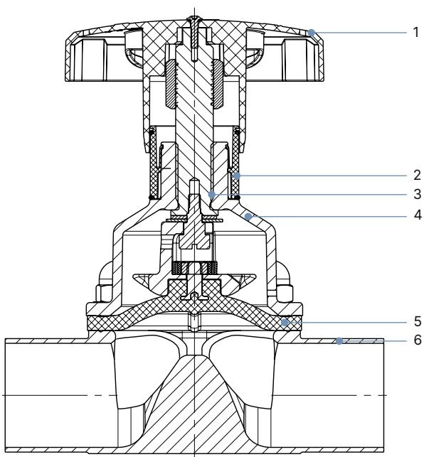
BURKERT 20099135 incorporates a modular mechanical structure designed to isolate mechanical drive parts completely from fluid-contact surfaces:
| Item | Component | Material |
|---|---|---|
| 1 | Handwheel | Polyphenylene sulphide (PPS), size M (Ø 110 mm) |
| 2 | Visual Position Indicator | Polyamide (PA) with stroke graduation scale |
| 3 | Valve Spindle | Stainless steel 1.4305 |
| 4 | Diaphragm Bonnet | Polyphenylene sulphide (PPS) |
| 5 | Diaphragm | EPDM high-temperature (code AD / E04) |
| 6 | Valve Body | Precision-cast stainless steel 316L / 1.4435 (VG) |
Internal wetted surfaces of cast valve bodies (VG) are finished to a standard electropolished roughness of Ra ≤ 0.6 µm (NO16, ASME BPE SF6) or mechanically polished to Ra ≤ 0.76 µm (NO06, ASME BPE SF3 / DIN H2).
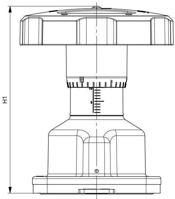
The manual actuator for diaphragm size 40 utilizes an M-size handwheel providing a 2.0 mm spindle slope per complete revolution:
| Diaphragm Size | Handwheel Size | Height H1 (Open) [mm] | Height H2 (Closed) [mm] | Handwheel Ø B [mm] | Spindle Slope per Turn [mm] |
|---|---|---|---|---|---|
| 32 | M | 129 | 115 | 110 | 2.0 |
| 40 | M | 134 | 116 | 110 | 2.0 |
| 50 | M | 149 | 125 | 110 | 2.0 |
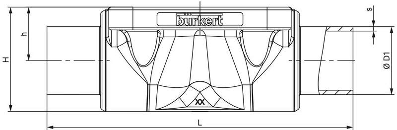
Dimensions correspond to the cast valve body (VG) with ASME BPE / DIN 11866 Series C welded ends:
| Diaphragm Size | Port Size DN [in] | Pipe Ø D1 [mm] | Wall Thickness s [mm] | Length L [mm] | Body Height h [mm] | Total Height H [mm] | Product Key |
|---|---|---|---|---|---|---|---|
| 20 | 3/4" | 19.05 | 1.65 | 119 | 18.0 | 32.8 | SA93 |
| 25 | 1" | 25.40 | 1.65 | 114 | 20.0 | 39.0 | SODF |
| 40 | 1 1/2" | 38.10 | 1.65 | 140 | 28.6 | 55.0 | SODH |
| 50 | 2" | 50.80 | 1.65 | 159 | 35.5 | 68.0 | SODI |
Flow rate data is measured at +20 °C with water at 4 bar valve inlet pressure and 3 bar valve outlet pressure. For diaphragm size 40 with cast valve body (VG) and 1 1/2" ASME BPE pipe connections, the nominal Kv rating is 35 m³/h (Cv 40.8 gpm).
Kv = 35.0 m³/h | Cv = 40.8 gpm | Medium Pressure = 0 to 10 bar
Applying excessive force to the handwheel reduces diaphragm operational life. The handwheel must only be rotated until the closed seat engagement is achieved:
| Diaphragm Size | Max Static Pressure [bar] | Static Tightness Torque (EPDM) [Nm] | Dynamic Tightness Torque (EPDM) [Nm] |
|---|---|---|---|
| 25 | 10 | 1.2 | 3.6 |
| 32 | 10 | 2.5 | 8.0 |
| 40 | 10 | 4.5 | 12.0 |
| 50 | 10 | 6.0 | 15.0 |
A tolerance of +10% applies to specified tightening torques.
| Diaphragm Size | Cast Body VG (EPDM) [Nm] | Cast Body VG (PTFE) [Nm] | Tube Body VP (EPDM) [Nm] | Tube Body VP (PTFE) [Nm] |
|---|---|---|---|---|
| 25 | 5 | 6 | 7 | 8 |
| 32 | 6 | 8 | 8 | 10 |
| 40 | 8 | 10 | 12 | 15 |
| 50 | 12 | 15 | 15 | 20 |
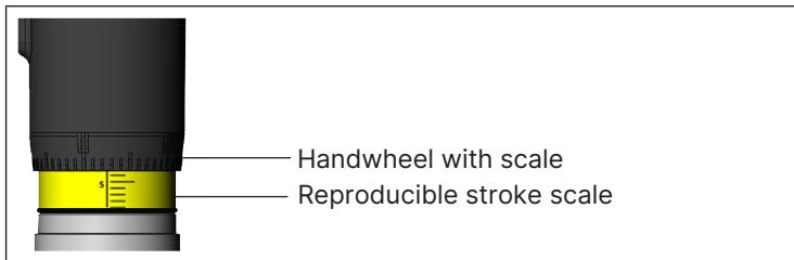
Turning the handwheel counterclockwise reveals the optical yellow indicator and its vertical stroke graduation scale. The graduated scale on the circumference of the handwheel provides 30 distinct angular positions per rotation, enabling reproducible stroke positioning.
Visual Indicator Position Note
Visibility of the yellow indicator band does not correlate directly with valve shut-off status. Seating closure must always be determined by feeling the positive stop or setting the internal closing limiter.
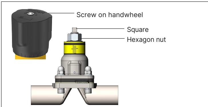
Type 2933 manual actuators feature an internal hexagon nut serving as a minimum stroke limiter to prevent over-tightening:
Limit Range Restriction
The minimum stroke closing limiter must only be set within the 0% to 25% opening stroke range. Never position the hexagon nut across the square drive area of the spindle.
BURKERT 20099135 can be installed in any orientation, though placing the actuator facing upwards is preferred. To achieve complete drainability in sanitary loops, specific pipeline orientation angles must be observed.
Self-Draining Alignment
Ensure self-draining by matching pipeline pitch to ASME BPE criteria. Orient the body marking on the port connection upward and position one of the bonnet relief bores at the lowest point to permit early leakage detection.
Disassembly Prior to Welding
Actuator and diaphragm components must be removed from the valve body before welding into process piping. Thermal conduction during welding permanently damages elastomeric diaphragms and plastic bonnets.
When operated under specified service limits, the PPS manual actuator is maintenance-free. Fastening screws should be checked and retightened crosswise following the first steam sterilisation cycle. Inspect the diaphragm for wear at intervals up to 100,000 switching cycles, or more frequently when managing abrasive process streams.
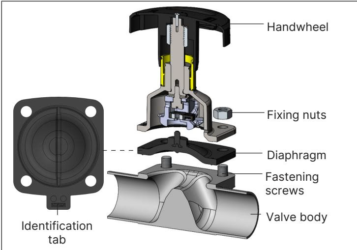
Diaphragm size 40 EPDM membranes utilize a threaded connection pin engaging the compressor drive:
| Item Description | Diaphragm Size | Material Code | Article No. |
|---|---|---|---|
| EPDM Replacement Diaphragm (AD) | 40 | EPDM E04 | 688426 |
| PTFE/EPDM Replacement Diaphragm (EA) | 40 | EPDM E04 / PTFE P05 | 20093073 |
| Advanced PTFE/EPDM Diaphragm (EU) | 40 | EPDM E04 / PTFE P06 | 20093084 |
| GYLON® / EPDM Laminate Diaphragm (ER) | 40 | PTFE L08 | 693180 |
| Inductive Proximity Switch M5 (Initiator) | 8 to 50 | Standard | 550412 |
| Inductive Proximity Switch M5 ATEX | 8 to 50 | ATEX Certified | 904779 |
| 4-Fold Nylon Handwheel Locking Mechanism | Size M (3 mm bracket) | Nylon | 93719475 |
Explore similar products in our catalog