Type 2032

BURKERT Type 2933 manually operated diaphragm valve. Features a compact, autoclavable design, visual position indicator, and ATEX/IECEx options. Available in sizes DN 6 to DN 100.
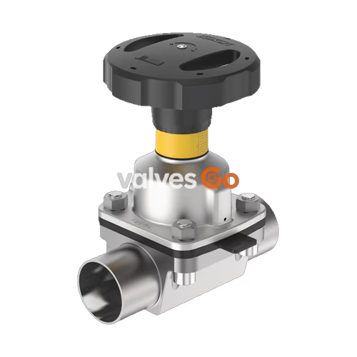
The BURKERT Type 2933 manually operated diaphragm valve consists of a manually operated actuator, a diaphragm, and a 2-way valve body. The manual actuator with a plastic or stainless steel handwheel is available with a diaphragm bonnet made of stainless steel or plastic and ensures use in hygienic or aggressive ambient conditions. The flow-optimised valve body with minimum dead space enables high flow values and a wide range of possible applications. The valve body and the diaphragms are available in all common materials and variants.
The actuator has a compact, autoclavable design and is compatible with all other Bürkert diaphragm valves. An explosion-proof ATEX/IECEx device variant is available. The manual actuator is equipped with an integrated visual position indicator, a reproducible stroke scale, and an adjustable closing limiter. The manual actuator can optionally be equipped with sensors for position feedback.
Family Models
This product family includes several variants sharing the same actuator and diaphragm technology:
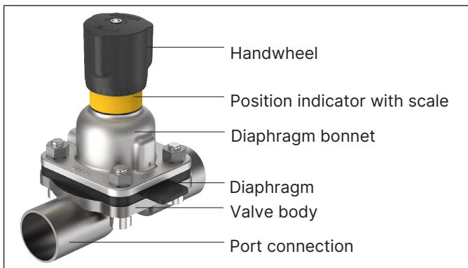 Example of the 2/2-way valve, Type 2933
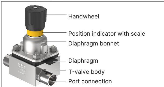 Example of the diaphragm valve with T-body, Type 2934
Explosion Protection (ATEX/IECEx)
If the device is used in a potentially explosive atmosphere, ensure proper grounding of the actuator and valve body to prevent electrostatic charging hazards. For plastic valve bodies, the actuator must be grounded separately. Only use cleaning agents certified for explosive environments.
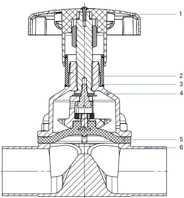
| No. | Element | Material |
|---|---|---|
| 1 | Handwheel | Polyphenylene sulphide (PPS), stainless steel 1.4308 |
| 2 | Visual position indicator | Polyamide (PA), Stainless steel 1.4305 |
| 3 | Valve spindle | Stainless steel 1.4305 |
| 4 | Diaphragm bonnet | Stainless steel 1.4308, polyphenylene sulphide (PPS) |
| 5 | Diaphragm | EPDM (AD), PTFE/EPDM (EA), advanced PTFE/EPDM (EU), laminate of GYLON® and EPDM (ER) |
| 6 | Valve body | Forged steel, tube, cast stainless steel, PVC-C, PVC-U, PP, PVDF |
The values are valid for valve bodies made from plastic and stainless steel (block material, forged, cast, and tube).
| Diaphragm size | Maximum permitted medium pressure [bar] (EPDM/FKM) | Maximum permitted medium pressure [bar] (PTFE/advanced PTFE/GYLON) |
|---|---|---|
| 8 to 40 | 10 | 10 |
| 50 | 7 / 10 (7 bar for PPS handwheel/bonnet) | 7 / 10 (7 bar for PPS handwheel/bonnet) |
| 65 to 80 | 10 | 10 |
| 100 | 6 | 6 |
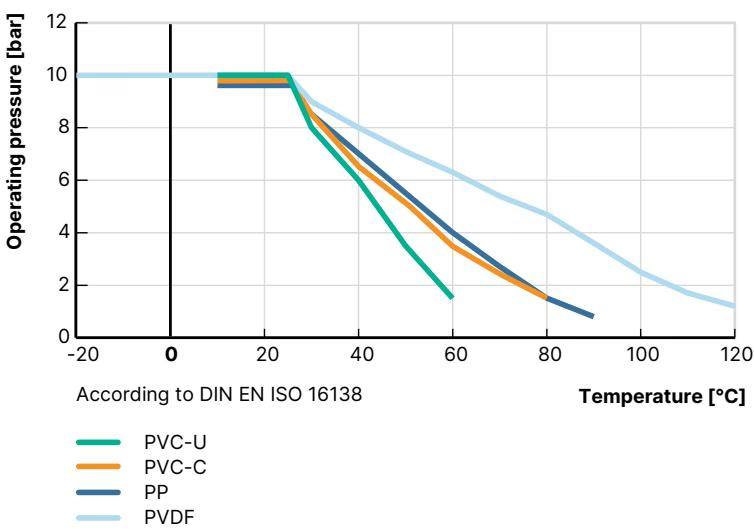
This information is important for material selection. Observe the permissible operating pressure depending on the medium temperature.
Note: The Kv values may vary slightly for different diaphragm materials. Measurement at +20 °C, 4 bar at valve inlet and 3 bar at valve outlet.
| Diaphragm size | Port connection DN | Kv value water [m³/h] (ASME BPE / DIN 11866 series C) |
|---|---|---|
| 8 | 1/4" | 0.7 |
| 8 | 3/8" | 1.6 |
| 8 | 1/2" | 1.5 |
| 15 | 1/2" | 3.1 |
| 15 | 3/4" | 6.5 |
| 20 | 3/4" | 8.4 |
| 25 | 1" | 15.5 |
| 40 | 1 1/2" | 37 |
| 50 | 2" | 66 |
| 65 | 2 1/2" | 110 |
| 80 | 3" | 160 |
| 100 | 4" | 235 |
Installation for Self-Draining
It is the responsibility of the installer and the operator to ensure self-draining. The self-draining angle depends on the valve body size and the inner diameter of the port connection. The marking on the port connection of the valve body serves as an orientation aid and must point upwards.
Explore similar products in our catalog