Type 2032

Burkert Type 2973 2/2-way manual diaphragm valve with forged stainless steel body, PTFE/EPDM diaphragm, and PPS handwheel. Suitable for sterile applications up to 10 bar.
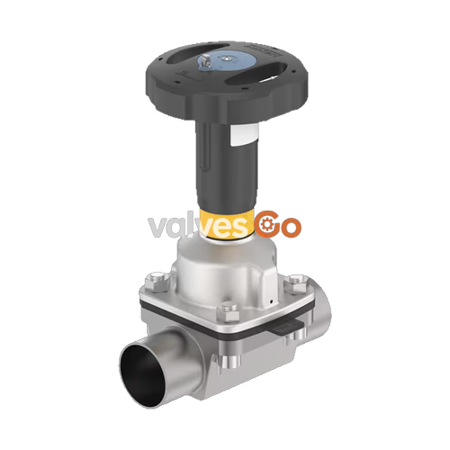
BURKERT Type 2973 is a manually operated 2/2-way diaphragm valve consisting of an actuator, a diaphragm, and a 2-way valve body. The manual actuator with a plastic handwheel allows for use in hygienic or aggressive environments. The flow-optimised and zero dead volume valve body enables high flow rates and versatile applications. The Type 2973 is equipped with a minimum and maximum stroke limiter and a locking mechanism. The actuator features a compact, autoclavable design and is compatible with all other Bürkert diaphragm valves.
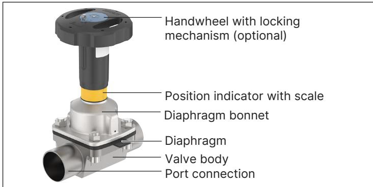
| Component | Material |
|---|---|
| Valve body | Forged stainless steel 316L/1.4435 BN2, Precision-cast stainless steel, Stainless steel tube, PVC-C, PVC-U, PP, PVDF |
| Actuator | Handwheel and diaphragm bonnet: PPS; Handwheel: PPS and diaphragm bonnet: stainless steel |
| Diaphragm | EPDM, PTFE/EPDM, advanced PTFE/EPDM, laminate made from GYLON® and EPDM, FKM |
INFO
When using plastic cover caps for hexagon nuts and hexagon bolts, the maximum ambient temperature is limited to 60 °C (temporarily: 80 °C).
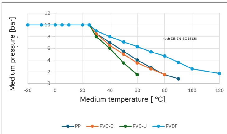
| Diaphragm size | Maximum permitted medium pressure (EPDM/FKM) | Maximum permitted medium pressure (PTFE/advanced PTFE/GYLON®) |
|---|---|---|
| 8 to 40 | 10 bar | 10 bar |
| 50 | 7 / 10 bar | 7 / 10 bar |
| 65 to 80 | 10 bar | 10 bar |
| 100 | 6 bar | 6 bar |
DANGER
Risk of injury due to high pressure and escaping medium. Switch off the pressure before working on the device or system. Vent or empty the lines.
Installation position is any, preferably with the actuator facing up. It is the responsibility of the installer and the operator to ensure self-draining.
Observe the rules for self-draining during installation:
WARNING
To prevent damage, dismantle the actuator and diaphragm before welding or bonding the valve body.
A minimum and maximum stroke limit can be set for Type 2973 (diaphragm sizes 15…50). An adjusting sleeve is used for this purpose.
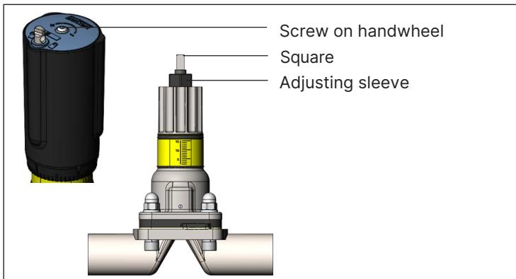
For Type 2973 (diaphragm size 15…50), a locking mechanism is available as an option to prevent accidental or unauthorised operation. The locking pin has a bore (Ø 3.8) and can be secured against unauthorised use with a padlock.
TIP
After the first steam sterilisation, or when required, retighten the fastening screws crosswise. After a maximum of 10⁵ switching cycles check the diaphragm for wear.
The following factors influence the service life of the diaphragm: diaphragm material, medium, medium pressure, medium temperature, and closing force. Replace the diaphragm if there are leaks and conduct regular inspections of the relief bore.
Explore similar products in our catalog