

PN16

Burkert 20108896 Type 8640 is a 6-bank pneumatic valve block with 19 mm station width, G 1/4 supply ports, D6 push-in bottom ports, 2-10 bar operating pressure, and single wiring.
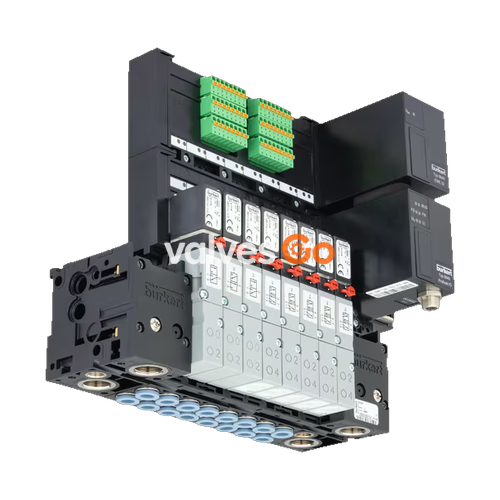
Burkert 20108896 Type 8640 is a pre-assembled 6-bank pneumatic valve block featuring a 19 mm station width, designed for DIN-rail and wall mounting in pneumatic automation systems. Configured for individual wiring without internal bus communication modules, the unit integrates 3/2-way pneumatic valve functions based on Type 5470 rocker pilot valves. It operates across an operating pressure range of 2.0 to 10.0 bar and accommodates neutral gases or compressed air at medium temperatures from 0 °C to 50 °C.
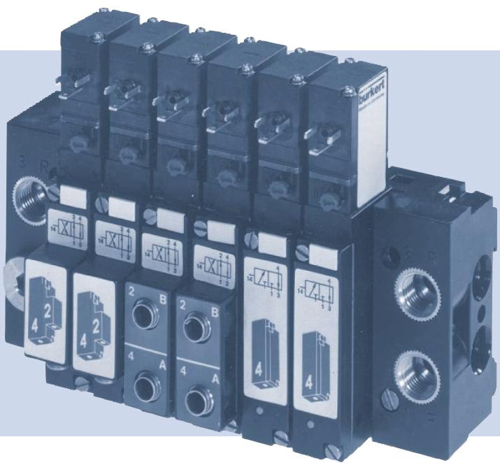
Pneumatic interconnection on this 6-bank block is routed through modular polyamide base modules, providing a shared G 1/4 supply port 1 (P) and exhaust port 3 (R), while each station directs control air through bottom-facing D6 mm push-in working ports. With standard electrical coils wired through Form C cable plugs, the valve block provides an IP20 baseline rating and reaches IP65 protection when using Type 2516 cable connectors with fitted flat seals.
| Specification Parameter | Value / Range |
|---|---|
| Product Type | Type 8640 Modular Valve Island Block |
| Article Number (SKU) | 20108896 |
| Width per Station | 19.00 mm |
| Valve Bank Configuration | 6 valve stations (6-bank) |
| Circuit Function | 3/2-way (CF C normally closed / CF D normally open configurable) |
| Solenoid Valve Series | Type 5470 (fitted with Type 6106 rocker pilot) |
| Orifice Size (DN) | DN 4.0 mm |
| Flow Rate Air (QNn) | 300 l/min (measured at +20 °C, 6 bar inlet, 1 bar pressure drop) |
| Operating Pressure Range | 2.00 bar to 10.00 bar (requires min. 2 bar differential between 1 and 3) |
| Medium Temperature | 0 °C to +50 °C (operation below 0 °C restricted to dried air) |
| Ambient Temperature | 0 °C to +55 °C |
| Operating Medium | Filtered dry compressed air (particle size max. 10 μm) or neutral gases (5 μm) |
| Compressed Air Quality | ISO 8573-1:2010, Class 7.4.4 |
| Supply Port 1 (P) / Exhaust 3 (R) | G 1/4 female thread |
| Working Connections 2 (A) / 4 (B) | Push-in coupling D6 mm (OD 6 mm) |
| Working Port Position | Valve bottom |
| Operating Voltage | 24 V DC (±10% tolerance, ripple ≤ 1 Vss) |
| Nominal Power per Coil | 1 W to 2 W |
| Duty Cycle | 100% continuous operation |
| Body / Seal Materials | Polyamide (PA) / Nitrile butadiene rubber (NBR) |
| Degree of Protection | IP20 baseline; IP65 with Type 2516 cable plug |
| Mounting Standard | DIN rail EN 50022 (35 x 7.5 mm / 35 x 15 mm) or M4 wall mounting |
Differential Pressure Requirement
Pneumatic switching requires a minimum pilot pressure differential between pressure port 1 (P) and exhaust port 3 (R) of at least 2.0 bar (at least 70% of operating pressure).
Each station on the Burkert 20108896 assembly incorporates a Type 5470 pneumatic valve driven by an integrated Type 6106 rocker pilot valve. The pilot system utilizes a tilting armature on a low-friction bearing pivot inside the pilot body. Because the minimal tilting movement causes negligible friction, basic lubrication is eliminated, delivering high switching stability across extended duty cycles.
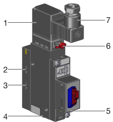
| Item | Designation | Technical Function |
|---|---|---|
| 1 | Pilot Valve Type 6106 | Rocker-action electromagnetic pilot actuation |
| 2 | Exhaust Port 3 (R) | Common manifold exhaust collector |
| 3 | Pressure Port 1 (P) | Common main air feed passage |
| 4 | Working Port 4 (B) | Station outlet connection (sealed or active depending on circuit mode) |
| 5 | Working Port 2 (A) | Station outlet connection (D6 push-in coupling) |
| 6 | Manual Override | Mechanical rotary override for manual actuation |
| 7 | Cable Plug Connection | Electrical interface for DIN EN 175301-803 Form C plugs |
Manual override allows testing without electrical energization. To actuate, push the yellow override actuator down and turn it 90° clockwise until it hits the mechanical stop. The mechanism remains locked in the active position and does not reset automatically. After manual testing, rotate the override back 90° counter-clockwise to resume electrical control.
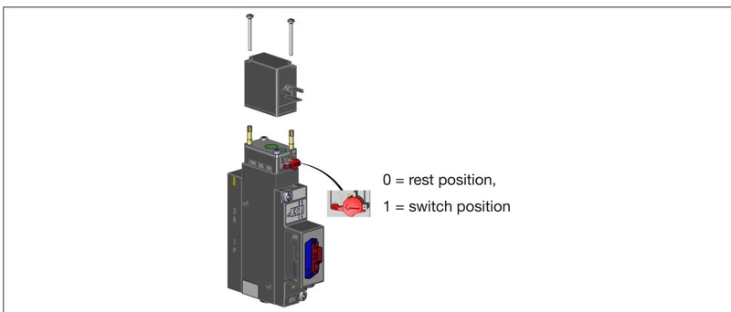
Manual Override Operational Rule
Operate the manual override only when the electrical coil is de-energized. Prior to electrical start-up, verify that all manual override actuators across all 6 stations are returned to their zero position.
Burkert 20108896 utilizes modular MP05 polyamide base rail blocks linked by integrated latching hooks and tabs, sealed by elastomer O-rings between adjacent modules.
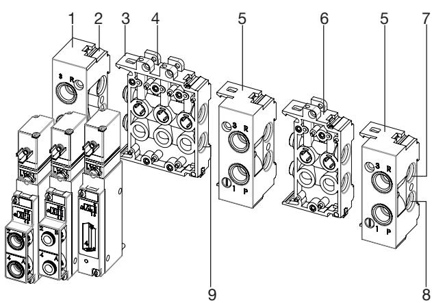
| Item | Designation | Functional Description |
|---|---|---|
| 1 | Left Connection Module | Pneumatic supply block with G 1/4 port connections |
| 2 | Latch Tab | Upper mating interface for interlocking adjacent base rails |
| 3 | Latch Hook | Lower hook element engaging alignment grooves |
| 4, 6 | Base Modules (3-fold / 2-fold) | Intermediate station modules housing individual valve bodies |
| 5 | Right Connection Module | End closure or secondary pressure supply terminal |
| 7 | Exhaust Channel 3 (R) | Shared exhaust manifold collector duct |
| 8 | Supply Channel 1 (P) | Shared primary pressure supply passage |
| 9 | O-Rings | Channel seals seated between adjoining modular blocks |
Assembly commences from the left connection module. Before interlocking blocks, coat O-rings lightly with pneumatic-compatible grease or oil. Insert the 3 recess O-rings at the rear mating surface of each valve body before securing the valve to the base module with 2 mounting screws tightened to 0.6 ±0.1 Nm.
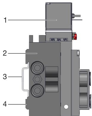
Supply line 1 (P) and exhaust line 3 (R) use G 1/4 female threads. Station working ports 2 (A) and 4 (B) are fitted with integrated push-in couplings sized for 6 mm outside diameter (OD) pneumatic tubing.
High Pressure Hazard
Depressurize and drain all pneumatic pipework before connecting or disconnecting fittings. Flapping uncoupled air lines present severe impact hazards. Verify full tubing engagement before applying pressure.
| Port Size | Port Designation | Recommended Torque | Maximum Permissible Torque |
|---|---|---|---|
| G 1/4 | Supply Port 1 (P), Exhaust Port 3 (R) | 4 to 7 Nm | 20 Nm |
| G 1/8 | Auxiliary ports and A/B station outlets | 3 to 6 Nm | 7 Nm |
Hose lines must possess a minimum hardness of 40 Shore D (per DIN 53505 / ISO 868) with outside diameter tolerance complying with DIN 73378 (within ±0.1 mm of nominal). Tubing must be cut square, burr-free, and inserted fully past the internal retention claws to the mechanical stop.
| Hose Material | Outside Diameter (OD) | Permitted OD Tolerance |
|---|---|---|
| Polyamide (PA) | 3 mm to 10 mm | ±0.08 mm |
| Polyamide (PA) | 12 mm to 16 mm | ±0.10 mm |
| Polyurethane (PU) | 3 mm to 8 mm | ±0.10 mm |
| Polyurethane (PU) | 10 mm to 16 mm | ±0.15 mm |
To ensure positive retention, push-in joints must withstand the minimum tensile forces specified in DIN ISO 14743:2020:
| Tubing Outer Diameter | Minimum Tensile Force (PA Hose) | Minimum Tensile Force (PU Hose) |
|---|---|---|
| 3 mm (1/8") | 60 N | 25 N |
| 4 mm (5/32") | 70 N | 50 N |
| 6 mm (1/4") | 120 N | 100 N |
| 8 mm (5/16") | 170 N | 150 N |
| 10 mm (3/8") | 250 N | 200 N |
| 12 mm (1/2") | 300 N | 200 N |
Tubing Retention Recommendation
For polyurethane (PU) tubing operating near dynamic thermal or pressure boundaries, install internal support sleeves (ID 20099400) to reinforce tubing wall stability inside push-in retention claws.
Burkert 20108896 operates on individual wiring. Each valve position connects independently using a DIN EN 175301-803 Form C cable plug (such as Type 2516).
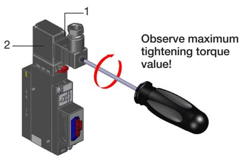
| Item | Component | Specification / Requirement |
|---|---|---|
| 1 | Flat Profile Seal | Elastomer sealing gasket between plug body and coil face |
| 2 | Cable Plug Type 2516 | DIN EN 175301-803 Form C socket connector |
| Screw | Central Fastening Screw | Tightening torque: max. 0.3 Nm (1 Nm on coil socket base) |
Electrical Safety and Earthing
Verify that the protective earth conductor is connected and seated firmly. Continuity resistance between the coil ground pin and the valve body must measure ≤ 0.1 Ω when tested at 12 V / 1 A.
Each solenoid coil can be detached and rotated by 180° by loosening the M2 retaining screws. When reinstalling the coil, tighten screws in two progressive increments: 0.1 Nm (±0.05 Nm), followed by 0.2 Nm (±0.05 Nm).
Prior to initial operation, confirm that the supply voltage matches the coil marking (24 V DC ±10%), the air supply delivers 2.0 to 10.0 bar clean dry air, and ports 1 and 3 are not reversed.
| Observed Fault | Potential Cause | Corrective Action |
|---|---|---|
| Valves fail to actuate | Missing or insufficient DC operating voltage | Verify voltage supply at plug terminals against type label (24 V DC ±10%). |
| Manual override locked in manual position | Rotate manual override 90° counter-clockwise to zero position. | |
| Insufficient primary supply pressure | Confirm supply pressure is ≥ 2.0 bar with adequate volumetric air flow. | |
| Delayed valve shifting or blow-off at exhaust | Supply pressure below operating threshold | Check for flow restrictions; maintain ≥ 2.0 bar dynamic pressure under load. |
| Exhaust duct backpressure from clogged silencer | Clean or replace silencer; install larger expansion volume if required. | |
| Particulate contamination in pilot or seat area | Flush exhaust channels with short pressure pulses or replace contaminated pilot valve. | |
| External air leakage at manifold | Missing or pinched O-rings between base blocks | Disassemble module joint, verify seal channels, and replace damaged O-rings. |
| Deformed flat gasket between valve and base plate | Inspect valve interface seal, reseat gasket evenly, and torque M4 screws to 0.6 Nm. |
Explore similar products in our catalog


