Up to 99.8% Efficiency

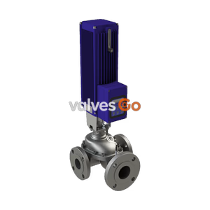
BURKERT 20120433 (Type 3361) electromotive 2-way globe control valve with DN 25 PN25 flanged body, 24 V DC AG2 1300 N linear actuator, SAFEPOS fail-safe pack, Kvs 3.2, stainless steel seat, and büS interface.
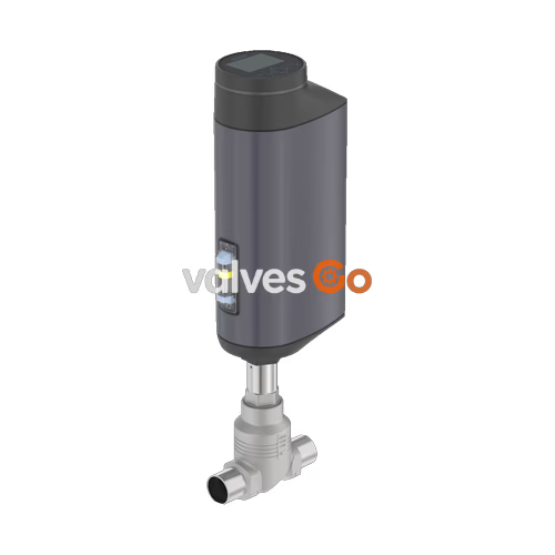
BURKERT 20120433 (Type 3361) is an electromotive 2-way globe control valve engineered for continuous flow regulation of liquids, gases, and steam under demanding industrial conditions. Constructed with a DN 25 DIN EN 1092-1 PN 25 flanged cast stainless steel body (CF3M), the unit pairs with an AG2 electric linear actuator delivering 1300 N nominal positioning force at a linear speed of 6 mm/s. The internal trim features a 10 mm (3/8") orifice seat paired with an equal-percentage control cone (50:1 theoretical rangeability), providing an exact nominal flow capacity of Kvs 3.2 m³/h (Cv 3.7 gpm). Flow direction is configured below the seat (port 2 to port 1, against closing direction) to eliminate fluid hammer during closure.
The valve includes an internal SAFEPOS energy-pack emergency power module. Upon interruption of the primary 24 V DC power supply, this integrated capacitive module automatically provides the energy required to return the valve to the normally closed safety position. The device features an integrated positioner with an illuminated 360° LED optical status ring, a digital display module with configuration pushbuttons, terminal strip wiring via cable bushings, and an internal büS service communication interface. The assembly complies with ATEX and IECEx Zone 2/22 protection standards and meets EC Regulation 1935/2004 for food contact.
| Technical Parameter | Specification / Rating |
|---|---|
| Article Number | 20120433 |
| Type Family | 3361 |
| Valve Configuration | 2-way globe control valve |
| Nominal Diameter | DN 25 (NPS 1) |
| Port Connection Type | Flange according to DIN EN 1092-1 PN 25 FTF 1 (DIN EN 558-1) |
| Pressure Rating | PN 25 (DIN EN 1333), Class 150 (DIN EN 1759) |
| Operating Pressure | 0 to 25 bar(g) |
| Seat Orifice Size | 10 mm (3/8") |
| Flow Coefficient Kvs | 3.2 m³/h (water at +20 °C) |
| Flow Coefficient Cv | 3.7 gal/min |
| Flow Characteristic | Equal percentage (theoretical rangeability 50:1) |
| Seat Seal Tightness | Class IV according to DIN EN 60534-4 (metallic seat) |
| Actuator Size / Nominal Force | AG2 / 1300 N |
| Positioning Speed | 6 mm/s |
| Typical Closing Time | 3.3 s (3,300 ms) |
| Dead Band | ±0.1% of stroke range |
| Supply Voltage | 24 V DC ± 10% (max. residual ripple 10%) |
| Operating Current | AG2: Max. 3 A (including 1 A SAFEPOS charging current) |
| Duty Cycle | 100% continuous |
| Standby Power | 2 to 5 W |
| Medium Temperature | -10 °C to +150 °C |
| Ambient Temperature | -25 °C to +65 °C (subject to temperature derating) |
| Maximum Medium Viscosity | Up to 600 mm²/s |
| Ingress Protection | IP65 / IP67 according to DIN EN 60529, NEMA 4X |
| Protection Class | Class III (DIN EN 61140) |
| Fail-Safe Mechanism | SAFEPOS energy-pack (normally closed on power loss) |
| Electrical Interface | Terminal strip with cable bushings (3 x M20) |
| Analogue Set-point Input | 0/4 to 20 mA (70 Ω input impedance), 0 to 5/10 V (22 kΩ) |
| Analogue Feedback Output | 0/4 to 20 mA (load 0 to 800 Ω), 0 to 5/10 V (max. 10 mA) |
| Digital Inputs / Outputs | 1 digital input (0 to 5 V = log 0, 10 to 30 V = log 1); 2 digital outputs (PNP, max. 100 mA) |
| Digital Protocol | büS service interface (micro USB Bürkert Communicator connection) |
| Explosion Protection | ATEX / IECEx: II 3 G Ex ec IIC T4 Gc, II 3 D Ex tc IIIC T135°C Dc |
| Food Contact Compliance | Regulation (EC) 1935/2004 according to manufacturer declaration |
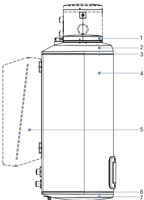
| Item | Actuator Component | Material |
|---|---|---|
| 1 | Display housing / blind cover | PPS (stainless steel 1.4301 for ATEX/IECEx variants) |
| 2 | Actuator cover | PPS |
| 3 | Housing seal | EPDM |
| 4 | Actuator main housing | Powder-coated aluminium |
| 6 | Lower housing seal | EPDM |
| 7 | Actuator base | PPS |
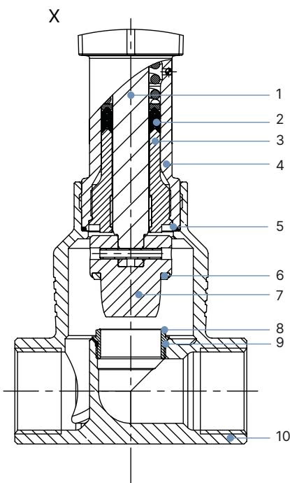
| Item | Wetted / Body Component | Material Specification |
|---|---|---|
| 1 | Spindle | Stainless steel 1.4401 (316) / 1.4404 (316L) |
| 2 | Spindle seal | PTFE V-seals (filled) with spring compensation |
| 3 | Spindle guide | Stainless steel 1.4404 (316L) |
| 4 | Packing gland tube | Stainless steel 1.4401 (316) |
| 5 | Valve body seal | Graphite or PTFE |
| 6 | Seat seal | Stainless steel 1.4571 |
| 7 | Control cone | Stainless steel 1.4571 |
| 8 | Valve seat | Stainless steel 1.4571 |
| 9 | O-ring valve seat | EPDM or PTFE |
| 10 | Valve body | Cast stainless steel CF3M |
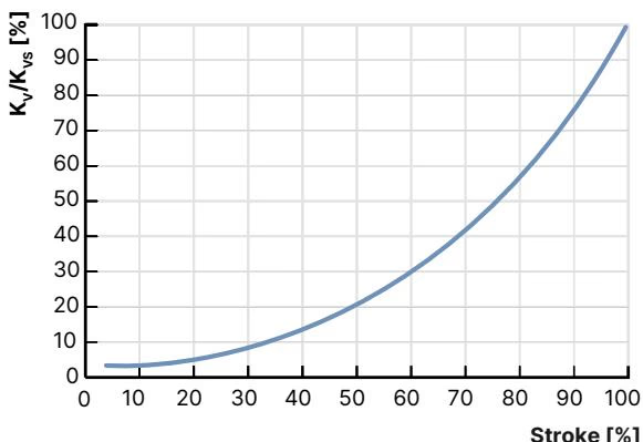
Flow characteristic conforms to equal percentage according to DIN EN 60534-2-4 with a theoretical rangeability of 50:1. The table below outlines the fluidic values for flow entering below the valve seat for liquids, steam, and gases across calibrated valve stroke percentages for DN 25 with seat size 10 mm:
| Port DN | Seat Size | Actuator Force | Max. ΔP [bar] | Rangeability | 5% | 10% | 20% | 30% | 40% | 50% | 60% | 70% | 80% | 90% | 100% (Kvs) |
|---|---|---|---|---|---|---|---|---|---|---|---|---|---|---|---|
| DN 25 | 10 mm | 1300 N | 25 (Leakage Cl. IV) | 50:1 | — | 0.12 | 0.16 | 0.20 | 0.33 | 0.52 | 0.77 | 1.2 | 1.8 | 2.6 | 3.2 m³/h |
For DN 25 port bodies, alternative seat sizes from 3 mm to 25 mm can be fitted into the body geometry to adapt the flow range:
| Dimension Designation | DN 25 Flange Value (DIN EN 1092-1 PN 25 FTF 1) |
|---|---|
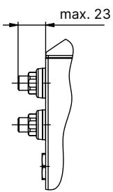
| Overall Actuator Height H1 (Standard variant) | 446 mm (raised by ~2 mm when closed without sealing function) |
| Overall Height H2 (with Fieldbus gateway) | 518 mm |
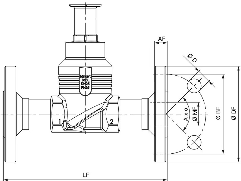
| Flange Face-to-Face Length (LF) | 160 mm |
| Flange Outer Diameter (∅ DF) | 115 mm |
| Bolt Circle Diameter (∅ BF) | 85 mm |
| Flange Thickness (AF) | 18 mm |
| Bolt Hole Diameter (∅ D) | 14 mm |
| Number of Bolt Holes and Pattern (A x α) | 4 × 90° |
| Body Port Bore Diameter (∅ MF) | 29.7 mm |
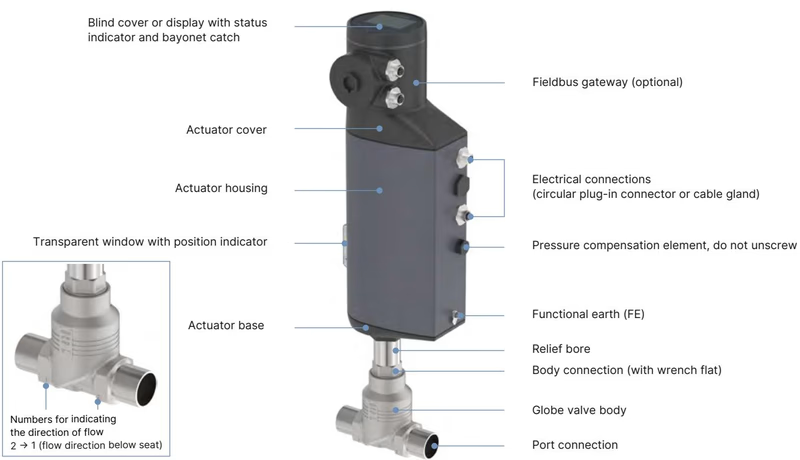
Article 20120433 utilizes an internal terminal strip accessed via 3 x M20 cable glands for industrial field wiring. The electronic position controller processes analogue set-point signals and provides status feedback:
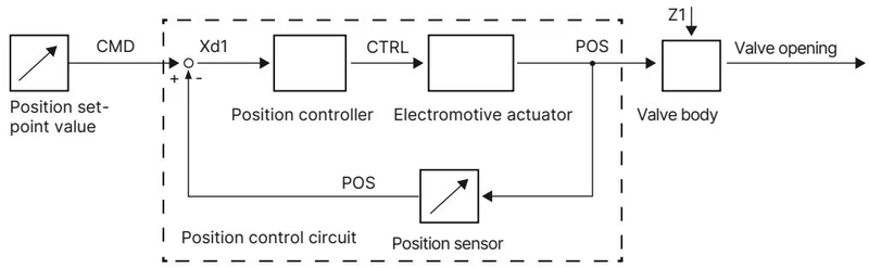
The electromotive linear actuator incorporates a brushless DC motor, mechanical planetary reduction gearing, and a precision recirculating ball screw spindle that translates rotational motion into linear thrust. An integrated non-contact position sensor continuously registers the actual valve stroke (POS) and compares it with the incoming set-point value (CMD). When a deviation (Xd1) occurs, the electronics drive the motor via variable CTRL output to reposition the spindle within a dead band of ±0.1%.
The factory-installed SAFEPOS energy-pack consists of high-capacity storage capacitors integrated within the actuator housing. If the 24 V DC power supply fails, the module immediately supplies reserve power to drive the ball screw until the valve reaches the defined safety position (normally closed). The energy pack reaches full charge within 120 seconds of line power activation and offers an operating lifespan up to 10 years.
The valve position can be actuated manually via software, display keys, or mechanical override:
Mechanical Manual Override Limit
Do not exceed the maximum permissible torque of 2 Nm when engaging the mechanical manual override. Applying excessive torque at stroke end limits will cause mechanical transmission damage.
After remounting the actuator or replacing internal trim components, the position controller must be recalibrated to the physical valve stroke using the X.TUNE function:
Medium Pressure Restriction During X.TUNE
Never initiate the X.TUNE function while process media is under pressure in the piping system. Executing calibration under line pressure leads to inaccurate stroke baseline recording and uncontrolled valve operation.
When reassembling the actuator onto the DN 25 valve body, renew the body graphite seal (part of seal set), coat the body connection external threads with Klüberpaste UH1 96-402, and torque the body connection hex to the specified rating:
| Connection Component | DN 25 Specified Torque |
|---|---|
| Body Connection to Actuator | 60 ± 3 Nm (44 ± 2 lbf·ft) |
| Valve Seat Thread (DN 25, Seat size 10 mm) | 40 + 5 Nm |
| Spindle Guide Bushing (Spindle ∅ 14 mm) | 25 Nm |
| Actuator Base Screws (4 screws, crosswise) | 5 Nm |
| Display Cover / Bayonet Screws | 1.1 Nm |
Explore similar products in our catalog