


Up to 99.8% Efficiency

BURKERT 20121116 Type 3360 is an electromotive 2-way angle seat control valve with DN 25 SMS 3008 weld ends, 24 V DC AG2 actuator, PTFE seat seal, Class VI tightness, and 16 m³/h flow capacity.
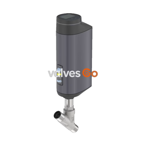
BURKERT 20121116 (Type 3360) is an electromotive 2-way angle seat control valve designed for demanding continuous throttling applications where high positioning dynamic and tight shut-off are required. The assembly comprises an electromotive linear actuator (actuator size AG2) driving a stainless steel 1.4571 control cone against a PTFE seat seal via a ball screw spindle system. This specific article is configured with welded port connections according to SMS 3008 in size DN 25 (pipe dimensions 25.0 x 1.2 mm), operating on a 24 V DC supply voltage. The integrated positioner regulates the stroke with a positioning speed of 6 mm/s, an active position control dead band of ±0.1%, and a closing time of 3.3 s. Flow passes below the valve seat (direction 2 → 1), delivering a nominal flow coefficient Kv of 16 m³/h (Cv 18.7 gpm) with a modified equal percentage flow characteristic across a nominal pressure span from 0 to 25 bar(g).
| Parameter | Value |
|---|---|
| Article Number | 20121116 |
| Valve Type | Type 3360 angle seat control valve |
| Nominal Diameter (DN / NPS) | DN 25 (NPS 1), tube dimensions 25.0 x 1.2 mm |
| Port Connection Type / Standard | Welded connection / SMS 3008 |
| Flow Direction | Against closing direction (below seat, 2 → 1) |
| Valve Body Material | Stainless steel CF3M |
| Seat Seal Material | PTFE (soft seal, leakage class VI per DIN EN 60534-4) |
| Seat Diameter | 25 mm (1") |
| Control Cone Material | Stainless steel 1.4571 |
| Spindle Diameter | 14 mm (stainless steel 1.4401 / 1.4404) |
| Nominal Pressure Rating | PN 25 (DIN EN 1333), Class 150 (DIN EN 1759) |
| Operating Pressure Range | 0.00 to 25.00 bar(g) |
| Flow Coefficient Kv / Cv | Kv = 16 m³/h (water at +20 °C) / Cv = 18.7 gal/min |
| Flow Characteristic | Modified equal percentage (theoretical rangeability Kvs/Kv0 = 50:1) |
| Actuator Size / Driving Force | AG2 / 1300 N |
| Positioning Speed | 6 mm/s (AG2 with 1300 N motor force) |
| Typical Closing Time | 3.3 s (3300 ms) |
| Dead Band of Position Control | ± 0.1 % |
| Operating Voltage | 24 V DC ± 10 % (maximum residual ripple 10 %) |
| Operating Current | Maximum 3 A (AG2 at peak load; +2 A at minimum operating temperature) |
| Standby Power Consumption | 2 to 5 W |
| Duty Cycle | 100 % continuous |
| Safety Position on Power Loss | Blocked in last static position (fail-freeze, without SAFEPOS energy-pack) |
| Medium Temperature Range | -10 °C to +130 °C (operating limits for PTFE seal) |
| Ambient Temperature Range | -25 °C to +65 °C (without additional functional modules) |
| Ingress Protection | IP65 / IP67 (DIN EN 60529), NEMA 4X |
| Protection Class | Class III (DIN EN 61140) |
| Weight | Approximately 5.5 kg (AG2 actuator and DN 25 valve body) |
BURKERT 20121116 complies with key European directives and international industrial standards:
The wetted section and actuator assembly use corrosion-resistant materials engineered for clean industrial, chemical, and food processes.
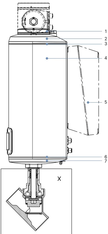
| Item | Component | Material |
|---|---|---|
| 1 | Blind cover (standard) | PPS (polyphenylene sulphide) |
| 2 | Actuator cover | PPS |
| 3 | Housing seal | EPDM |
| 4 | Actuator housing | Aluminium, powder-coated |
| 6 | Seal ring | EPDM |
| 7 | Actuator base | PPS |
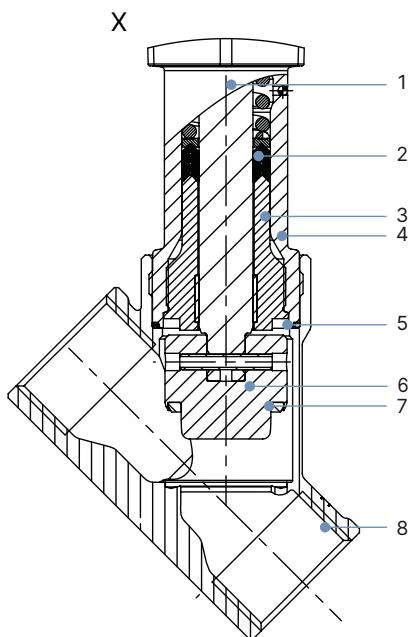
| Item | Component | Material |
|---|---|---|
| 1 | Spindle (ø 14 mm for DN 25) | Stainless steel 1.4401 (316) / 1.4404 (316L) |
| 2 | Spindle packing gland seal | PTFE V-seals (filled) with spring compensation |
| 3 | Spindle guide | Stainless steel 1.4404 (316L) |
| 4 | Packing gland tube | Stainless steel 1.4401 (316) |
| 5 | Valve body seal | Graphite seal ring |
| 6 | Control cone | Stainless steel 1.4571 |
| 7 | Seat seal | PTFE seal washer (clamped in stainless steel 1.4571) |
| 8 | Valve body | Stainless steel CF3M |
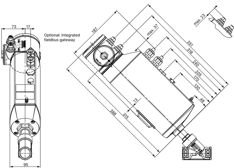
For DN 25 (NPS 1) with standard blind cover:
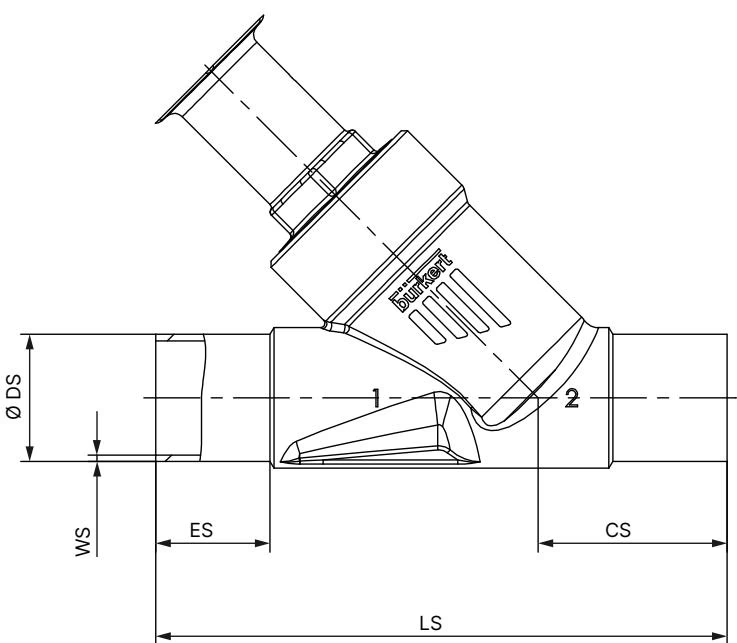
Dimensions for SMS 3008 and metric welded connections in mm:
BURKERT 20121116 uses circular M12 connectors and cable feed-through for electrical integration. Operating voltage and field communication connect through designated multi-pin ports.
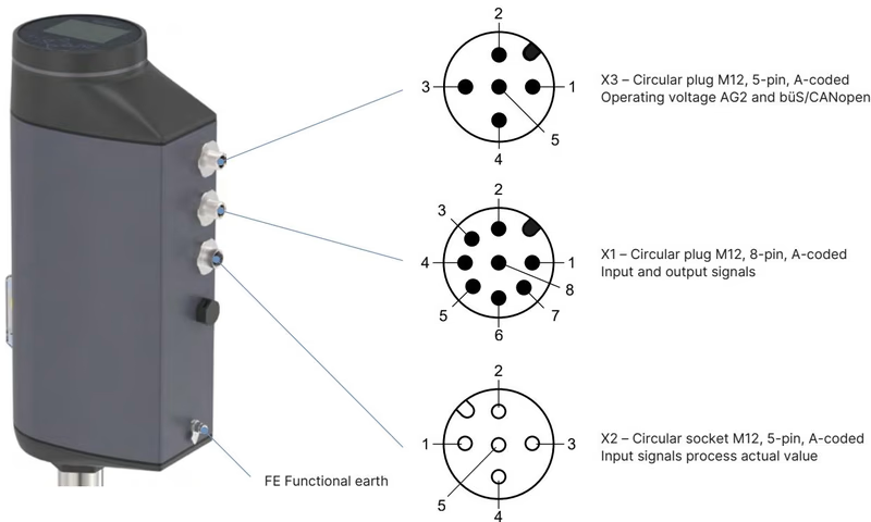
| Pin | Signal Assignment |
|---|---|
| 1 | Digital input + (0 to 5 V = log "0", 10 to 30 V = log "1") |
| 2 | GND for digital input and digital outputs |
| 3 | Digital output 2 + (PNP, max. 100 mA) |
| 4 | Digital output 1 + (PNP, max. 100 mA) |
| 5 | Analogue output - (0/4 to 20 mA or 0 to 5/10 V) |
| 6 | Analogue output + |
| 7 | Set-point value / Analogue input - (galvanically isolated) |
| 8 | Set-point value / Analogue input + (0/4 to 20 mA, input resistance 70 Ω; 0 to 5/10 V, 22 kΩ) |
| Pin | Signal Assignment |
|---|---|
| 1 | CAN Shield / shield |
| 2 | Operating voltage +24 V DC ± 10 % |
| 3 | GND / CAN_GND |
| 4 | CAN_H |
| 5 | CAN_L |
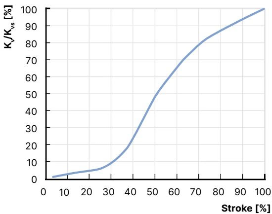
The modified equal percentage flow profile provides stable throttling control across a theoretical rangeability of 50:1. The initial opening region follows an engineered progression where angularity is observed starting at the KvR threshold at 5% of stroke.
| Valve Size | Seat Size | Actuator Force | Seat Seal | Operating Pressure | 5% | 10% | 20% | 30% | 40% | 50% | 60% | 70% | 80% | 90% | 100% (Kvs) |
|---|---|---|---|---|---|---|---|---|---|---|---|---|---|---|---|
| DN 25 | 25 | 1300 N (AG2) | PTFE | 25 bar(g) | 0.34 | 0.36 | 0.62 | 1.5 | 5.2 | 8.9 | 11.5 | 13.0 | 14.2 | 15.4 | 16.0 |
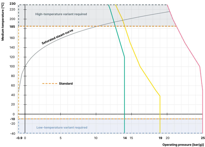
Process limits are governed by the nominal pressure curve according to DIN EN 12516-1 (PN 25) and ASME B16.34 (Class 150). For PTFE soft-sealed trim, the continuous medium temperature range extends from -10 °C up to +130 °C. The valve achieves bubble-tight Class VI shut-off across this entire thermal range without requiring a downstream isolation valve.
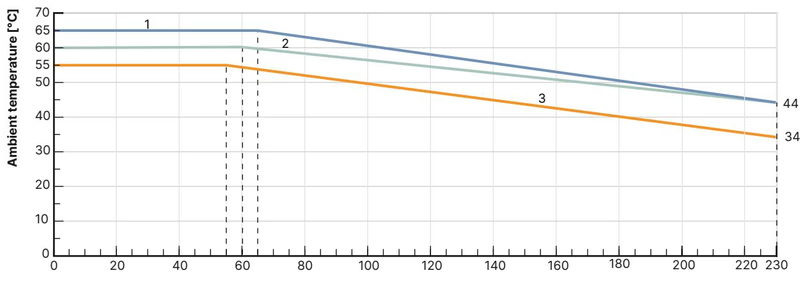
The allowable ambient temperature depends directly on the process fluid temperature:
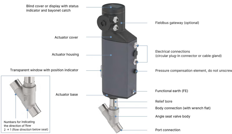
BURKERT 20121116 uses a brushless DC electromotor coupled to an internal reduction gear and precision recirculating ball screw spindle. This converts rotational energy directly into linear thrust without pneumatic air supplies. In an unpowered standstill, the gear design maintains mechanical self-locking, keeping the valve firmly seated or positioned against maximum media pressure.
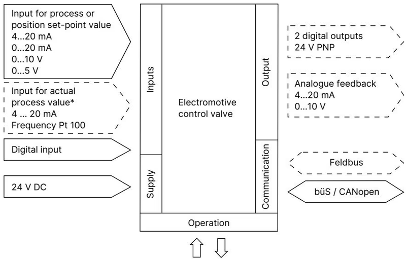
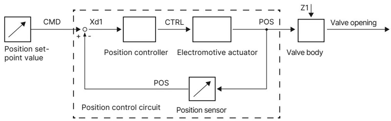
The internal non-contact displacement sensor tracks the real-time linear spindle position (POS). The built-in positioner compares POS with the set-point value (CMD) supplied via analogue input (0/4..20 mA or 0..5/10 V). When a system deviation (Xd1) occurs, the electronics drive the motor via variable CTRL until the actual valve stroke matches the command within ±0.1% dead band.
Safety Position on Power Failure
Article 20121116 is configured without the SAFEPOS energy-pack storage module. If electrical supply voltage fails, the actuator does not drive to an open or closed safety end position; instead, it remains mechanically blocked in its last current position (fail-freeze).
Local configuration is managed beneath the blind cover without requiring an external display module.
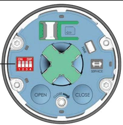
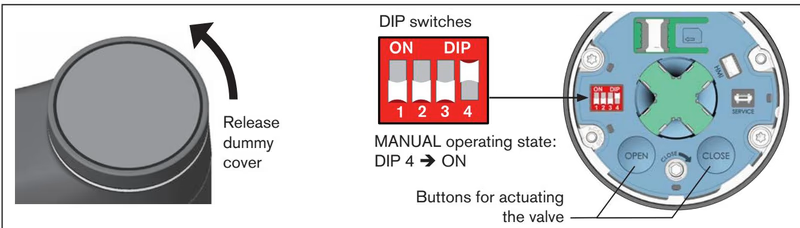
Under MANUAL operating mode:
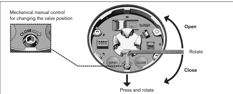
De-energized Operation Only
The mechanical manual override must only be actuated in a de-energized state. Never turn the override socket while supply voltage is active.
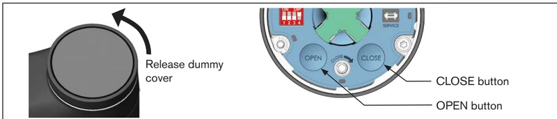
Whenever the actuator is remounted onto the valve body, or if the packing gland or control cone has been serviced, the automatic X.TUNE calibration routine must be executed.
Zero Medium Pressure Required
Never run the X.TUNE function under process medium pressure. If X.TUNE is started while pipeline pressure is applied, the controller will establish incorrect mechanical stroke limits, causing uncontrolled flow or actuator failure.
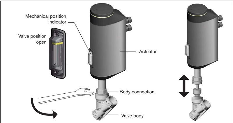
Residual Pressure Hazard
Before opening or disassembling the valve, isolate the line, discharge line pressure, and drain hazardous medium.
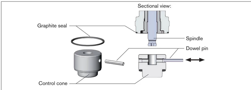
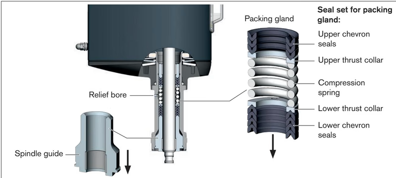
| Joint Location | Fastener / Component | Tightening Torque |
|---|---|---|
| Body connection | DN 25 body union thread | 60 ± 3 Nm (44 ± 2 lbf ft) |
| Spindle guide | Spindle guide ø 14 mm (DN 25) | 25 Nm |
| Manual override | 3 mm Allen key mechanical drive | Max. 2.0 Nm |
| Blind cover / Display module | Bayonet fastening | Rotate to align vertical marks |
| Component Description | DN / Size | Order Article No. |
|---|---|---|
| Control cone set (PTFE / stainless steel, with dowel pin & graphite seal) | DN 25 (Seat 25) | 170318 |
| Packing gland seal set (PTFE V-seals, seal ring, lubricant) | Spindle ø 14 mm (DN 25 to 50) | 285722 |
| VA spindle guide for packing gland | Spindle ø 14 mm (DN 25 body) | 246579 |
| Modified socket wrench for packing gland replacement | SW21 (Spindle ø 14 mm, DN 25 to 50) | 683223 |
| Body holding clamp fixture | DN 25 to DN 50 | 693771 |
| Replacement blind cover (PPS plastic) | AG2 standard | 277881 |
| M12 female cable plug, 8-pin, A-coded, length 2 m (for X1 signals) | Multi-conductor | 919061 |
| M12 female cable plug, 4-pin, A-coded, length 5 m (for X3 power) | 24 V DC supply | 918038 |
| USB-büS interface set 1 (Type 8923 with PC power supply) | Service interface | 772426 |
| USB-büS interface set 2 (Type 8923 without power supply) | Service interface | 772551 |
| Recommended thread lubricant paste | Klüberpaste UH1 96-402 | Available from Klüber |
Explore similar products in our catalog


