

PN16

BURKERT 20128182 (Type 8652 AirLINE) is a 16-slot pneumatic valve island with PROFIBUS DPV1, aluminium AirLINE Quick adapter, integrated check valves, pneumatic HotSwap, and 32 digital inputs.
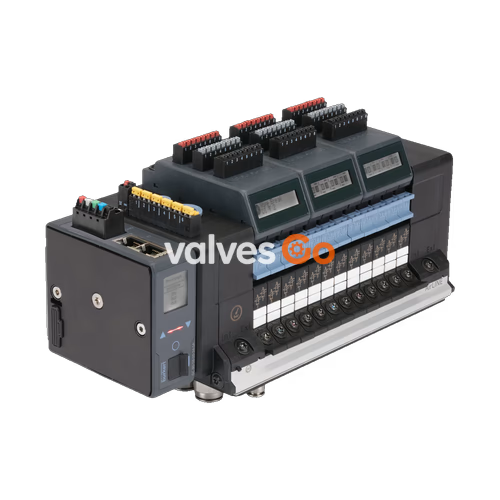
BURKERT 20128182 (Type 8652 AirLINE) is an electro-pneumatic 16-valve-slot valve island developed for process automation applications. Configured with a PROFIBUS DPV1 fieldbus interface via a 9-pin Sub-D connection, article 20128182 integrates five 3/2-way Circuit Function C (normally closed) solenoid valves on positions 1 through 5, while positions 6 through 16 are sealed with blind plates. The mechanical base utilizes an anodised aluminium AirLINE Quick adapter plate designed for bottom or wall cutout mounting in control cabinets, routing all pneumatic connections directly through the cabinet wall. Process connections feature brass push-in fittings with D10 mm for main air supply and D6 mm for working ports.
Type 8652 AirLINE incorporates an integrated LC display providing status and diagnostic readouts in plain text and symbols. To safeguard process continuity, the island includes integrated check valves in exhaust ducts 3 (R) and 5 (S) to prevent unintended actuator movement caused by backpressure spikes, as well as a pneumatic HotSwap mechanism on supply duct 1 (P) enabling online valve replacement under pressure with an approximate flow reduction of only 3%.
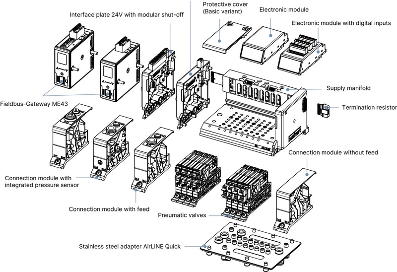
Article 20128182 is delivered with the following factory-assembled hardware configuration:
| Parameter | Factory Configuration |
|---|---|
| Article Number | 20128182 |
| Basic Model Type | 8652 AirLINE Standard |
| Valve Slot Count | 16 PCE |
| Valve Positions 1 to 5 | 3/2-way Solenoid Valve, Circuit Function C (CF-C), normally closed |
| Valve Positions 6 to 16 | Blind plates (dummy valves) |
| Digital Inputs | 32 DI total across 4 electronic input modules (El. module 1 to 4 with DI) |
| Fieldbus Module | PROFIBUS DPV1 (Sub-D 9-pin interface) |
| Pneumatic Supply Connection 1 (P) | Push-in connector D10 mm, Brass |
| Working Connections 2 and 4 | Push-in connectors D6 mm, Brass |
| AirLINE Quick Adapter Material | Aluminium |
| Pilot Air Mode | Internal auxiliary pilot air |
| Intermediate Feed Modules | 1 PCE (integrated pneumatic intermediate supply) |
| Check Valves | Integrated in exhaust ducts 3 (R) and 5 (S) |
| Pneumatic HotSwap | Integrated in pressure duct 1 (P) |
| Operating Pressure Range | -1.00 bar to 10.00 bar (vacuum to 10 bar) |
| Auxiliary Pilot Pressure | 3.00 bar to 10.00 bar |
| Operating and Ambient Temperature | -10.00 °C to +55.00 °C |
| Enclosure Rating | IP20 (open assembly) / IP65 (in closed enclosure with AirLINE Quick) |
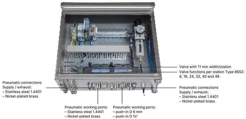
AirLINE Quick enables the valve island to mount directly onto the floor or wall of a control cabinet. This direct interface eliminates internal bulkhead fittings and cabinet-internal pneumatic piping, allowing users to reduce cabinet volume and installation assembly time.
| Feature | Technical Specification |
|---|---|
| Adapter Plate Material | Stainless steel 1.4301 or anodised aluminium (Article 20128182: Aluminium) |
| Pneumatic Fittings Material | Stainless steel 1.4401 or nickel-plated brass (Article 20128182: Brass) |
| Valve Function Capacity | 8, 16, 24, 32, 40, and 48 valve functions |
| Supply / Exhaust Ports | Push-in D10 mm, 3/8" |
| Working Ports | Push-in D6 mm, 1/4" |
| Permissible Mounting Positions | Control cabinet floor, control cabinet wall |
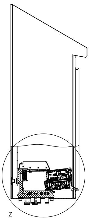
When installing the valve island inside the control cabinet, clearance dimensions to the cabinet front edge and rear wall must be maintained to ensure proper insertion and removal when utilizing the HotSwap function.
INFO
HotSwap operation allows single pneumatic valves to be dismounted and replaced while the remaining valve slots maintain system pressure. When active, flow rate QNn is reduced by approximately 3% through the HotSwap non-return mechanism.
Type 8652 valve islands feature an 11 mm grid per station. Article 20128182 represents the 16-valve-slot version equipped with an intermediate supply module.
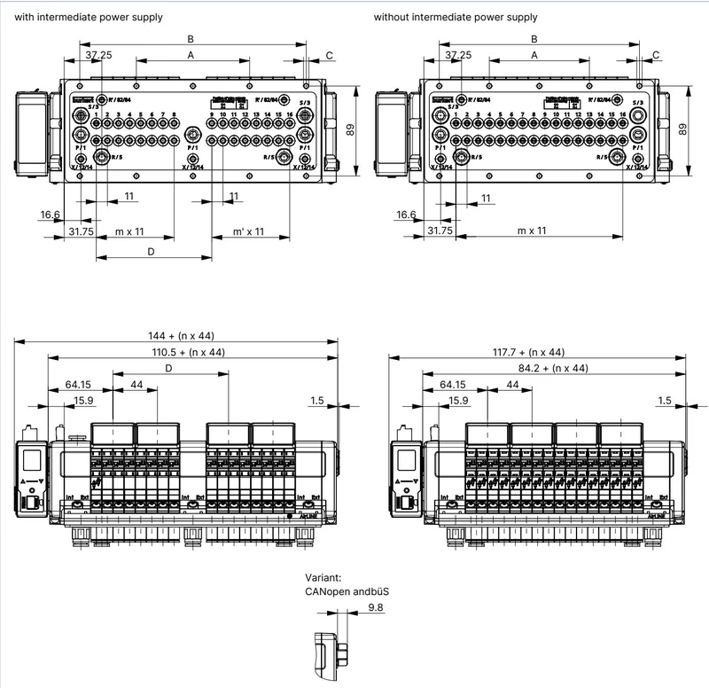
| Island Variant | A [mm] | B [mm] | C [Mounting Screws] | D [mm] | m | m' | n |
|---|---|---|---|---|---|---|---|
| 16-fold with intermediate supply | 112 | 224 | 10 × M5 | 114.3 | 7 | 7 | 4 |
| 20-fold with intermediate supply | 134 | 268 | 10 × M5 | 158.3 | 11 | 7 | 5 |
| 24-fold with intermediate supply | 156 | 312 | 10 × M5 | 158.3 | 11 | 11 | 6 |
| 16-fold without intermediate supply | 99 | 198 | 10 × M5 | — | 15 | — | 4 |
| 20-fold without intermediate supply | 121 | 242 | 10 × M5 | — | 19 | — | 5 |
| 24-fold without intermediate supply | 143 | 286 | 10 × M5 | — | 23 | — | 6 |
(Note: For 4-fold: A=66 mm, C=4×M5, m=3, n=1; 8-fold: A=35 mm, B=111 mm, C=8×M5, m=7, n=2; 12-fold: A=77 mm, B=154 mm, C=10×M5, m=11, n=3).
| Characteristic | Technical Specification |
|---|---|
| Housing Material | PA (Polyamide) |
| Seal Material | NBR and PUR |
| Station Width | 11 mm per valve slice |
| Maximum Number of Valve Slots | Up to 24 slots (16 slots populated on 20128182) |
| Maximum Number of Controllable Valves | Up to 48 valve functions |
| Manual Override | Latching, spring return (optional: lockable) |
| Nominal Operating Mode | Continuous operation (100% ED duty cycle) |
| Switching Time | Measured according to ISO 12238 standard |
| Nominal Flow Rate QNn (Air) | 310 l/min (measured at +20 °C, 6 bar inlet pressure, 1 bar differential pressure) |
| Pressure Range | Vacuum to 10 bar (-1 bar to 10 bar) |
| External Pilot Air Supply | 3 bar to 10 bar |
| Operating Voltage | 24 V DC (±10%, residual ripple 1 Vss) |
| Power Consumption per Valve | 0.7 W nominal (0.175 W after internal power reduction) |
| Current Consumption per Valve | 29 mA nominal (10 mA after internal power reduction) |
| Electrical Protection Class | Class III according to DIN EN 61140, VDE 0140 |
| Operating Medium | Oil-free or lubricated dry compressed air, neutral gases (5 µm filter recommended) |
| Compressed Air Quality | ISO 8573-1:2010, Class 7.4.4 |
| Ambient and Medium Temperature | -10 °C to +55 °C |
| Storage Temperature | -20 °C to +60 °C |
| Degree of Protection | IP20 (standard installation); IP65 (inside closed enclosure with AirLINE Quick) |
| NEMA Enclosure Rating | Type 4X in closed enclosures (with stainless steel variant) |
The valve terminal utilizes separate power feeds for communication logic and pneumatic valve coils to allow independent safety disconnection.
Power to communication electronics and the display module connects via a 5-pin spring-loaded terminal block (wire cross-section ≤ 1.5 mm²):
| Pin Assignment | Wire Colour | Signal Description |
|---|---|---|
| 1 | Red | 24 V DC |
| 2 | White | CAN_H (büS connection) |
| 3 | Green | SHIELDING |
| 4 | Blue | CAN_L (büS connection) |
| 5 | Black | 0 V DC (GND) |
Pneumatic coil operating power connects via an independent 2-pin spring-loaded terminal block on the interface plate:
| Terminal | Wire Colour | Signal Description |
|---|---|---|
| 1 | Red | AUX 24 V DC |
| 2 | Black | 0 V DC (GND) |
Article 20128182 connects to PROFIBUS DPV1 networks using a standard Sub-D 9-pin female socket:
| Pin | Signal | Description |
|---|---|---|
| 1 | Shield | Cable shield / Protective earth |
| 2 | M24 | 0 V DC output (optional) |
| 3 | RxD/TxD-P | Receive / Transmit data positive (B-line) |
| 4 | CNTR-P | Control signal P (optional) |
| 5 | DGND | Data ground (0 V) |
| 6 | +5 V | +5 V DC termination power supply |
| 7 | +24 V | +24 V DC output (optional) |
| 8 | RxD/TxD-N | Receive / Transmit data negative (A-line) |
| 9 | CNTR-N | Control signal N (optional) |
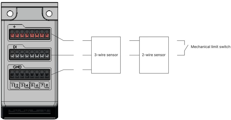
Article 20128182 includes four 8DI electronic modules, providing 32 digital input channels to read process feedback signals such as limit switches directly at the valve terminal. The 24 V DC sensor power is supplied internally from the electronic module, with current limited to a maximum of 30 mA per digital input channel.
| Property | Value / Specification |
|---|---|
| Sensor Compatibility | 2-wire sensors, 3-wire sensors (10–30 V), mechanical limit switches |
| Switching Thresholds | V_OFF = 0 V to 5 V; V_ON = 10 V to 30 V |
| Input Current at V_ON | Max. 5.7 mA per channel (typical at 24 V DC) |
| Input Impedance | > 4 kΩ |
| Galvanic Isolation | None; all channels share a common reference potential |
| Maximum Cable Length | < 30 m |
| Conductor Cross-Section | Pluggable screw terminal, 0.14 mm² to 1.5 mm² (AWG 28–16) |
| Diagnostic Capabilities | Wire-break detection (2-wire sensors); short-circuit detection (3-wire sensors) |
| Sensor State / Diagnostic | 3-Wire Sensor | 2-Wire Sensor | Mechanical Limit Switch |
|---|---|---|---|
| Sensor actuated | Yes | Yes | Yes |
| Sensor not actuated | Yes | Yes | Yes |
| Short circuit | Yes | — | — |
| Wire break | — | Yes | — |
Type 8652 supports standard Type 6534 solenoid valves and SIA variants for safety shut-off. Article 20128182 is fitted with five Type 6534 Circuit Function C valves (Article 20102334) and eleven blind plates (Article 335779).
| Circuit Function | Orifice [mm] | QNn Air [l/min] | Pressure Range [bar] | Opening Time [ms] | Closing Time [ms] | Voltage | Article No. (incl. screws) |
|---|---|---|---|---|---|---|---|
| C (CF C): 3/2-way NC servo-controlled, manual override | 4 | 270 | Vac. to 10 (Aux 3–10) | 15 | 15 | 24 V DC | 20102334 (Ref 20088974) |
| C (CF C): 2 × 3/2-way NC servo-controlled, manual override | 4 | 270 | Vac. to 10 (Aux 3–10) | 15 | 15 | 24 V DC | 301374 (Ref 296031) |
| D (CF D): 2 × 3/2-way NO servo-controlled, manual override | 4 | 310 | Vac. to 10 (Aux 3–10) | 15 | 15 | 24 V DC | 301375 (Ref 296032) |
| H (CF H): 5/2-way servo-controlled, manual override | 4 | 290 | Vac. to 10 (Aux 3–10) | 20 | 25 | 24 V DC | 301376 (Ref 296033) |
| Z (CF Z): 5/2-way impulse variant, 2 coils, manual override | 4 | 290 | Vac. to 10 (Aux 3–10) | 20 | 25 | 24 V DC | 301377 (Ref 296034) |
| L (CF L): 5/3-way closed center, manual override | 4 | 275 | Vac. to 10 (Aux 3–10) | 15 | 15 | 24 V DC | 301380 (Ref 296036) |
| M (CF M): 5/3-way ventilated center, manual override | 4 | 300 | Vac. to 10 (Aux 3–10) | 20 | 20 | 24 V DC | 301379 (Ref 296035) |
| N (CF N): 5/3-way exhausted center, manual override | 4 | 300 | Vac. to 10 (Aux 3–10) | 20 | 20 | 24 V DC | 301381 (Ref 296039) |
| Blind Plate: Dummy valve for unused slot | — | — | — | — | — | — | 335779 (Ref 327614) |
SIA valves feature additional 2-pin coded terminal blocks allowing direct wiring to an external potential-free emergency contact (switching capacity 0.5 A / 24 V DC, wire cross-section 0.14–1.5 mm²):
| Circuit Function | Orifice [mm] | QNn Air [l/min] | Pressure Range [bar] | Opening Time [ms] | Closing Time [ms] | Voltage | Article No. (incl. screws) |
|---|---|---|---|---|---|---|---|
| C (CF C): 3/2-way NC SIA | 4 | 270 | Vac. to 10 (Aux 3–10) | 15 | 15 | 24 V DC | 20102335 (Ref 20092052) |
| C (CF C): 2 × 3/2-way NC SIA | 4 | 270 | Vac. to 10 (Aux 3–10) | 15 | 15 | 24 V DC | 338802 (Ref 336443) |
| H (CF H): 5/2-way SIA | 4 | 290 | Vac. to 10 (Aux 3–10) | 20 | 25 | 24 V DC | 338805 (Ref 336444) |
| L (CF L): 5/3-way closed center SIA | 4 | 275 | Vac. to 10 (Aux 3–10) | 15 | 15 | 24 V DC | 346830 (Ref 336523) |
Type 8652 valve islands hold hazardous location certifications when specified for Zone 2/22 and Class I, Division 2 environments:
| Certification Body | Identification Marking | Standards / Scope |
|---|---|---|
| ATEX | BVS 20 ATEX E 031 U II 3G Ex ec IIC Gc II 3D Ex tc IIIC Dc | EN/IEC 60079-0, EN/IEC 60079-7, EN/IEC 60079-31 |
| IECEx | IECEx BVS 20.0024 U Ex ec IIC Gc Ex tc IIIC Dc | IEC 60079-0, IEC 60079-7, IEC 60079-31 |
| cURus HazLoc (USA / Canada) | Class I, Zone 2, AEx ec IIC Gc / Ex ec IIC Gc U Class II, Zone 22, AEx tc IIIC Dc / Ex tc IIIC Dc U Class I, Div 2, Groups A, B, C, D Class II, III, Div 2, Groups F, G | ANSI/UL 60079-0, ANSI/UL 60079-7, CAN/CSA-C22.2 |
| UL Listed | cULus Listed | UL 61010-1, CAN/CSA-C22.2 No. 61010-1 |
| CCC | SITIIAS Certification | GB/T 3836.2021 (Explosive atmospheres) |
Special Conditions for Hazardous Locations
| Description | Article Number |
|---|---|
| 5-pin spring-loaded terminal (Power supply for communication and display) | 920180 |
| 2-pin spring-loaded terminal (Power supply for pneumatic valves AUX 24 V) | 920442 |
| M5 × 10 A2 DIN 6912 screw set for AirLINE Quick cabinet fastening (10 pcs) | 308661 |
| Height adapter for 16-valve base plate with intermediate supply | 754962 |
| Retaining plate for 16-valve base plate with intermediate supply | 60005568 |
| Blind plate for 16-valve base plate with intermediate supply | 754967 |
| Bürkert Communicator Software | Type 8920 |
| USB büS Interface Set 1 (Type 8923) for Bürkert Communicator software | 772426 |
| Fieldbus Gateway Type ME43 – PROFIBUS DP | 301803 |
Explore similar products in our catalog


