


Up to 99.8% Efficiency

BURKERT 20133323 (Type 3361) is an electromotive 2-way globe control valve with G 2" port, 32 mm seat, Kv 12 m³/h, 2500 N AG2 actuator, 24 V DC power, SAFEPOS storage, and IP65/IP67 protection.
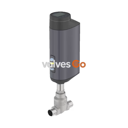
BURKERT 20133323 (Type 3361) is an electromotive 2-way globe control valve engineered for high-precision throttling in demanding industrial process applications. The valve assembly pairs a DN 50 cast stainless steel CF3M body with an AG2 electric linear actuator. Fitted with a G 2" threaded port and a reduced 32 mm (1 1/4") orifice seat, the valve achieves a nominal flow coefficient Kv of 12 m³/h (Cv 14 gpm) with an equal percentage 50:1 characteristic curve. Operating on 24 V DC, the brushless motor and ball screw mechanism drive the spindle at 4 mm/s with a nominal driving force of 2500 N, ensuring rapid response to setpoint variations while resisting process pressure fluctuations up to 25 bar(g).
Equipped with the factory-installed SAFEPOS energy-pack module, article 20133323 automatically drives the valve to a defined safety position (normally closed in delivery status) during power supply interruption. Local control and commissioning are provided through an integrated digital display module with navigation keys, supplemented by a 360° multi-color LED status ring. Fluid contact surfaces meet European Regulation (EC) 1935/2004 hygiene requirements. Ingress protection is rated to IP65/IP67 and NEMA 4X, supporting installation in damp, washdown, and aggressive process environments.
| Specification | Technical Value |
|---|---|
| Article Number | 20133323 |
| Valve Platform | Type 3361 Electromotive 2-way globe control valve |
| Pipeline Nominal Diameter | DN 50 (NPS 2) |
| Port Connection Type | G 2" Female internal thread (DIN ISO 228-1) |
| Orifice Size (Seat Diameter) | 32 mm (1 1/4") |
| Flow Coefficient Kv (Water) | 12 m³/h (Cv = 14 gpm) |
| Flow Characteristic | Equal percentage 50:1 |
| Flow Direction | Under seat (flow from port 2 to port 1) |
| Nominal Pressure Rating | PN 25 (DIN EN 1333), Class 150 (DIN EN 1759) |
| Operating Pressure Range | 0 to 25 bar(g) |
| Seat Leakage Class | Class IV (DIN EN 60534-4) |
| Medium Temperature Range | -10 °C to +185 °C |
| Ambient Temperature Range | -25 °C to +65 °C (see temperature derating limits) |
| Actuator Size / Force | AG2 / 2500 N nominal thrust |
| Linear Positioning Speed | 4 mm/s (for 2500 N force level) |
| Typical Closing Time | 6.6 s (6600 ms) |
| Position Control Dead Band | ±0.1% |
| Supply Voltage | 24 V DC ± 10% (max. 10% residual ripple) |
| Operating Current | Max. 3 A at max. load (incl. 1 A SAFEPOS charging current); +2 A at minimum ambient temp |
| Standby Power | 2 to 5 W |
| Duty Cycle | 100% continuous |
| Safety Feature | SAFEPOS energy-pack internal capacitive energy storage (NC default) |
| Electrical Connection | M12 circular connectors (A-coded) |
| Control Signals | Analogue 0/4 to 20 mA, 0 to 5/10 V, 1 DI, 1 AO, 2 DO |
| Communications | büS service interface (Bürkert Communicator Type 8920 compatible) |
| Local Interface | Display module with operation keys, 360° LED ring, mechanical position indicator |
| Protection Class | III (DIN EN 61140) |
| Degree of Protection | IP65 / IP67 (DIN EN 60529), NEMA 4X |
Article 20133323 complies with major regulatory and hygiene standards applicable to process control valves:
Food Contact Materials
All wetted metallic components are manufactured from high-grade 316-family stainless steels (CF3M, 1.4401/1.4404, 1.4571) and virgin PTFE packing seals, maintaining compliance with European Regulation (EC) 1935/2004.
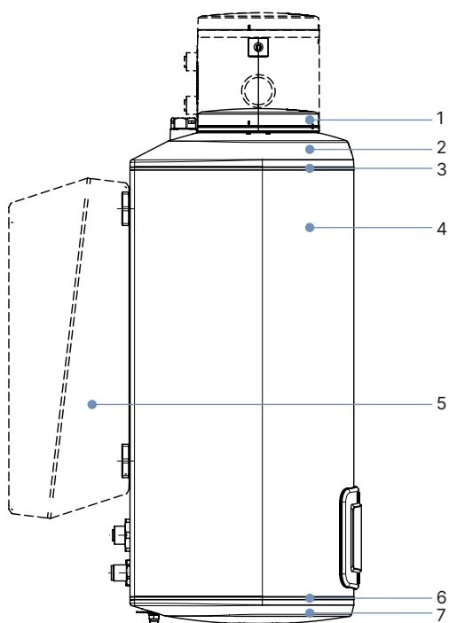
| Item | Component Description | Material |
|---|---|---|
| 1 | Display housing / blind cover / gateway housing | PPS (standard), stainless steel 1.4301 (for ATEX/IECEx) |
| 2 | Actuator cover | PPS |
| 3 | Seal rings | EPDM |
| 4 | Actuator housing | Cast aluminium, powder-coated |
| 6 | Actuator base seal | EPDM |
| 7 | Actuator base | PPS |
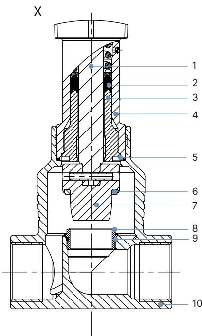
| Item | Component Description | Material |
|---|---|---|
| 1 | Spindle | Stainless steel 1.4401 (316) / 1.4404 (316L) |
| 2 | Spindle seal (packing gland) | Filled PTFE V-rings with spring compensation |
| 3 | Spindle guide | Stainless steel 1.4404 (316L) |
| 4 | Packing gland tube | Stainless steel 1.4401 (316) |
| 5 | Body gasket seal | Graphite or PTFE |
| 6 | Seat seal | Stainless steel 1.4571 (metallic seat sealing) |
| 7 | Control cone | Stainless steel 1.4571 |
| 8 | Valve seat | Stainless steel 1.4571 (screwed-in replaceable design) |
| 9 | Valve seat O-ring | EPDM or PTFE |
| 10 | Valve body | Stainless steel CF3M (cast 316L) |
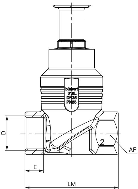
For pipe connection DN 50 (NPS 2) with G 2 internal thread and AG2 actuator without an external fieldbus gateway module, the key mounting dimensions are:
| Dimension Parameter | Value (mm) |
|---|---|
| Pipeline Nominal Diameter | DN 50 (NPS 2) |
| Overall Face-to-Face Body Length (LM) | 150 mm |
| Thread Depth (E - G thread) | 24 mm |
| Body Hexagon Width Across Flats (AF) | 70 mm |
| Total Actuator Height (H1 - Standard AG2) | 485 mm |
| Actuator Height (H2 - Fieldbus variant) | 557 mm |
| Additional Travel Clearance in Closed Position | Approx. 2 mm lift above seat |
| AG2 Actuator Weight | 5.5 kg (excluding valve body) |
Installation Recommendation
The valve can be installed in any orientation. Mounting with the linear actuator pointing vertically upward is recommended to facilitate display reading and routine packing inspection.
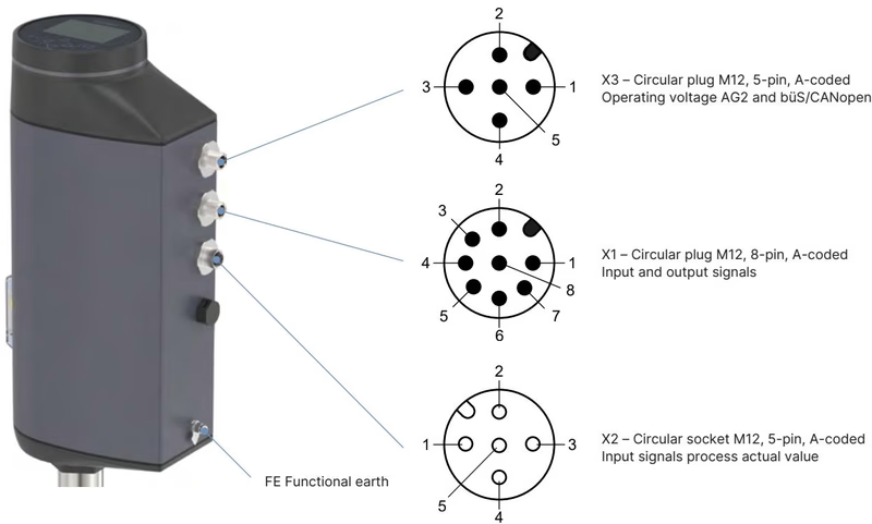
Article 20133323 employs M12 A-coded industrial circular connectors located at the actuator base. Power supply and service communications utilize circular plug X3, while input/output analogue and digital signals are handled via circular plug X1. For optional external process sensor feedback, circular socket X2 is provided.
| Pin Number | Signal Assignment | Electrical Specification |
|---|---|---|
| 1 | Digital input + | 0 to 5 V = log "0", 10 to 30 V = log "1" |
| 2 | GND | Common reference for digital input and digital outputs |
| 3 | Digital output 2 + | PNP transistor, current limited to 100 mA |
| 4 | Digital output 1 + | PNP transistor, current limited to 100 mA |
| 5 | Analogue output - | Galvanically isolated reference |
| 6 | Analogue output + | 0/4 to 20 mA (load 0 to 800 Ω) or 0 to 5/10 V (max. 10 mA) |
| 7 | Setpoint / Analogue input - | Galvanically isolated signal ground |
| 8 | Setpoint / Analogue input + | 0/4 to 20 mA (input resistance 70 Ω) / 0 to 5/10 V (22 kΩ) |
| Pin Number | Signal Assignment | Operating Function |
|---|---|---|
| 1 | CAN Shield / shield | Cable shield connection |
| 2 | Operating voltage + | +24 V DC ± 10% (max. residual ripple 10%) |
| 3 | GND / CAN_GND | Power supply ground and CAN reference |
| 4 | CAN_H | Bürkert system bus / CANopen dominant high |
| 5 | CAN_L | Bürkert system bus / CANopen dominant low |
| Pin Number | 4 to 20 mA Signal (External Sensor) | Frequency / Pt 100 Signal |
|---|---|---|
| 1 | Do not connect | Excitation / connection per sensor manual |
| 2 | Do not connect | Excitation / connection per sensor manual |
| 3 | Do not connect | Measurement bridge |
| 4 | Process actual value + (4..20 mA) | Signal input (>300 mVss, 0 to 1000 Hz) / Pt 100 (1 mA) |
| 5 | Process actual value GND | Reference ground |
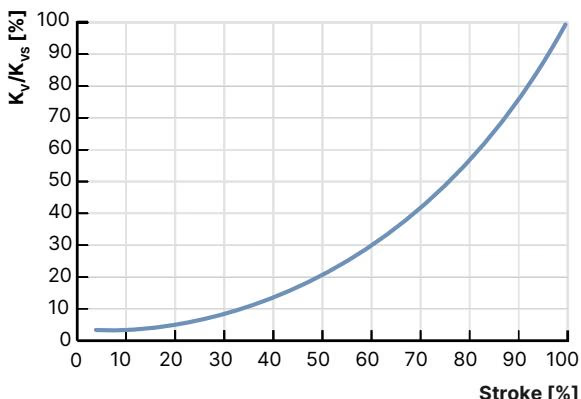
The Type 3361 globe control valve utilizes flow-optimized seats and parabolic control cones conforming to DIN EN 60534-2-4. Flow direction is directed under the seat (port 2 to 1), providing smooth control, cavitation reduction, and silent operation.
| Seat Size | Actuator Force | Max. Delta P (bar) | Rangeability | 10% | 20% | 30% | 40% | 50% | 60% | 70% | 80% | 90% | 100% (Kvs) |
|---|---|---|---|---|---|---|---|---|---|---|---|---|---|
| 32 mm | 2500 N (AG2) | 25 bar (Class IV) | 50:1 | 0.31 | 0.51 | 0.76 | 1.1 | 1.7 | 2.5 | 3.6 | 5.3 | 7.9 | 12.0 m³/h |
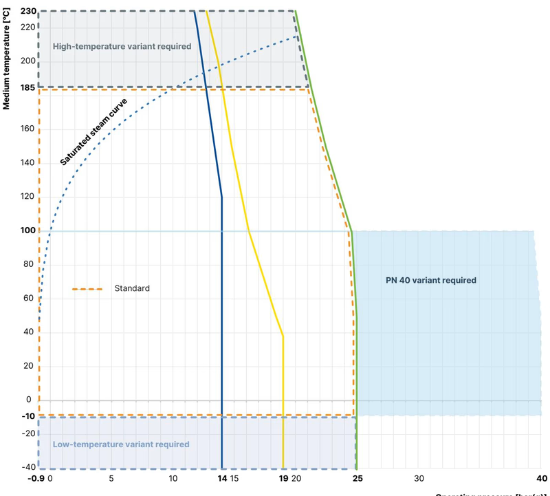
The maximum permitted working pressure of the stainless steel CF3M valve body is dictated by DIN EN 12516-1 (PN 25) and ASME B16.34 (Class 150):
Operating Pressure Limitation
According to Pressure Equipment Directive 97/23/EC, compressible fluids belonging to Group 1 (hazardous gases and vapors) are limited to a maximum working differential pressure of 20 bar(g) for seat size 32 mm.
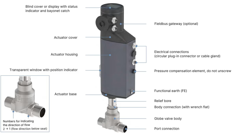
The AG2 actuator incorporates a brushless DC motor coupled to a planetary reduction gearbox and a precision ground ball screw spindle. This mechanical conversion delivers 2500 N linear thrust at a steady travel speed of 4 mm/s. The high holding torque of the ball screw holds the control cone firmly against fluid forces without continuous motor power draw, lowering idle consumption to between 2 and 5 W.
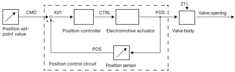
An internal contactless linear displacement transducer continuously monitors the actual spindle position (POS). The internal microprocessor compares POS with the setpoint position (CMD) provided via the analogue input (0/4-20 mA or 0-5/10 V) or digital büS network. The dead band is fixed at ±0.1%, preventing actuator hunting while delivering smooth, continuous positioning.
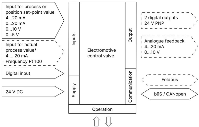
The integrated SAFEPOS energy-pack utilizes high-reliability internal electric storage cells. If main 24 V DC power is interrupted, the energy-pack powers the motor to drive the spindle to the configured safety position (factory default: fully closed). The energy-pack reaches full charge within 120 seconds of power restoration and continuously self-tests its remaining service capacity, generating an early warning when cell life degrades.
High Pressure Hazard
Depressurize the piping system and completely drain all process fluid before attempting to unscrew the actuator from the valve body or servicing any pressure-containing parts.
| Connection / Orifice Size | Valve Seat Tightening Torque | Actuator Body Connection Torque |
|---|---|---|
| DN 10 / 15 | 20 Nm (+3 Nm) | 45 ±3 Nm |
| DN 20 | 28 Nm (+3 Nm) | 50 ±3 Nm |
| DN 25 | 40 Nm (+5 Nm) | 60 ±3 Nm |
| DN 32 | 65 Nm (+5 Nm) | 65 ±3 Nm |
| DN 40 | 85 Nm (+8 Nm) | 65 ±3 Nm |
| DN 50 | 120 Nm (+8 Nm) | 70 ±3 Nm |
| DN 65 | — | 100 ±3 Nm |
| DN 80 | — | 120 ±5 Nm |
| DN 100 | — | 150 ±5 Nm |
Never Run X.TUNE Under Pressure
Running the X.TUNE calibration routine while the valve is under process pressure will corrupt the stroke limit settings and cause unstable closed-loop control. Ensure the line is completely unpressurized before running X.TUNE.
After reassembling the actuator onto the valve body or altering internal trim components, the X.TUNE routine must be executed:
| Description / Component Set | Application / Scope | Order Article Number |
|---|---|---|
| SAFEPOS energy-pack (AG2 replacement) | AG2 actuator emergency power module | 285834 |
| Packing Gland Seal Set | ø14 mm spindle, DN 25 to DN 50 | 285722 |
| Spindle Guide (Stainless steel) | ø14 mm spindle, DN 50 body connection | 246594 |
| Control Cone Set (Steel/Steel) | Seat size 32 mm, DN 50, stainless steel 1.4571 | 226957 |
| Valve Seat Set | Seat size 32 mm, DN 50, stainless steel 1.4571 | 262176 |
| Seat Installation Tool | DN 50 valve body seat removal/installation | 652609 |
| Modified Socket Wrench (Packing) | SW21 for ø14 mm spindle (DN 25 to DN 50) | 683223 |
| M12 Connection Cable (X3 Power) | 4-pole socket, length 5 m, unshielded | 918038 |
| M12 Connection Cable (X1 Signals) | 8-pole socket, length 2 m, shielded | 919061 |
| M12 Connection Cable (X2 Sensor) | 5-pole plug, length 2 m, shielded | 559177 |
| USB-büS Interface Set 1 | PC service set with power supply and cables | 772426 |
| USB-büS Interface Set 2 | PC service set without supplementary supply | 772551 |
| büS Adapter Cable | M12 to micro-USB for büS service port (0.3 m) | 774931 |
| Holding Device | For clamping DN 25 to DN 50 valve bodies | 693771 |
| SIM Card Module | Parameter storage and device cloning | 291773 |
Explore similar products in our catalog


