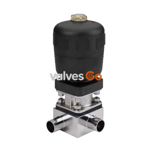
Type 2032

Burkert Type 2104 pneumatic diaphragm T-valve for decentralised automation. Features a stainless steel body, up to 10 bar pressure, and hygienic design.
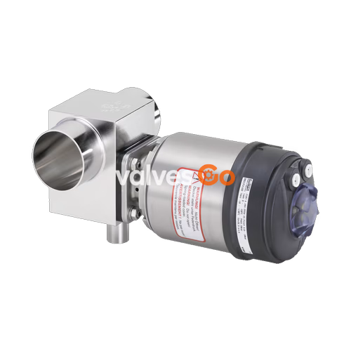
Burkert Type 2104 externally controlled diaphragm valve consists of a pneumatically operated piston actuator, a diaphragm, and a T-valve body. The proven and robust actuator with a stainless steel housing ensures reliable use in hygienic or aggressive ambient conditions. The flow-efficient valve bodies with little dead space enable high flow rates and a wide range of possible uses. The valve body and the diaphragm are available in all common materials and variants.
The actuator has a compact, autoclavable design with a large stainless steel housing and gap-free seals. The integration of automation units Type ELEMENT is possible in all configuration levels (can be retrofitted); a fieldbus interface can also be integrated. It is a highly integrated system consisting of a valve and an automation unit with integrated pilot air ducts (no intake of ambient air).
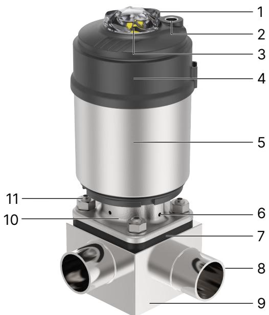
| Component | Description |
|---|---|
| 1 | Pilot air port 1 for CF A, CF B and CF I |
| 2 | Pilot air port 2 for CF I, exhaust port for CF A and CF B |
| 3 | Transparent cap with position |
| 4 | Actuator cover |
| 5 | Actuator housing |
| 6 | Relief bore |
| 7 | Diaphragm |
| 8 | Port connection |
| 9 | Valve body |
| 10 | Diaphragm bonnet |
| 11 | Body screw |
| Property | Value |
|---|---|
| Block body material | Stainless steel block material 1.4435 according to DIN EN 10088 and 316L according to ASTM A479 / A479M |
| Diaphragm material | EPDM (AD), PTFE/EPDM (EA), Advanced PTFE/EPDM (EU), laminate of GYLON® and EPDM (ER) |
| Actuator material | DN 08...65: PPS; DN 65...100: Stainless steel 1.4308 |
| Actuator casing | DN 08...65: Stainless steel 1.4561 (316Ti); DN 65...100: Stainless steel 1.4308 |
| Standard surface quality | Internally electrically polished: Ra ≤ 0.38 μm (ASME BPE SF4 / DIN HE4) |
| Operating medium | Neutral gases and liquids, highly purified, sterile, aggressive or abrasive mediums |
| Control medium | Neutral gases, air |
| Control Function | Description |
|---|---|
| Control function A (CF A) | Pneumatically operated T-valve. Normally closed by spring force. |
| Control function B (CF B) | Pneumatically operated T-valve. Normally opened by spring force. |
| Control function I (CF I) | Pneumatically operated T-valve on either side. Switching position dependent on external control. |
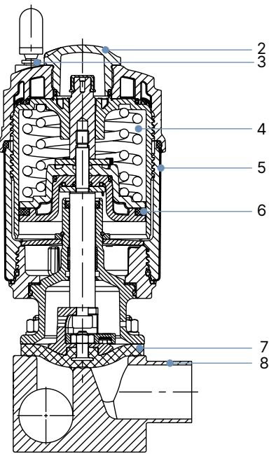
| No. | Element | Material |
|---|---|---|
| 1 | Ground terminal | Stainless steel 1.4301/1.4305 (only for ATEX/IECEx variant) |
| 2 | Transparent cap | Polysulfone PSU |
| 3 | Pilot air ports | Push-in connector PP (standard), Thread G 1/8" stainless steel 1.4305 |
| 4 | Actuator | Polyphenylene sulphide PPS |
| 5 | Cover | Stainless steel 1.4561 (316Ti) |
| 6 | Piston seal | FKM |
| 7 | Diaphragm | EPDM, PTFE/EPDM, advanced PTFE/EPDM, laminate of GYLON® and EPDM |
| 8 | Valve body | Stainless steel |
Risk of bursting due to overpressure
If the device bursts, escaping media may cause injuries, burns or scalds. Observe the maximum pilot and operating pressure values indicated on the type label.
Medium Temperature for Diaphragms:
Installation Position
The valve can be installed in any position, preferably with the actuator facing up. For pipelines, the inclination angles specified in the valid ASME BPE standard are recommended to ensure the valve is self-draining.
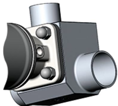
Weld the valve body into the pipeline: The diaphragm and actuator can be damaged when welding the valve body into the pipeline. In the case of devices with a welded connection, remove the actuator and diaphragm from the valve body before installation. After welding the surface of the valve body, smooth by sanding if necessary and clean the valve body carefully before reinstalling the actuator.
Explore similar products in our catalog