

PN16

BURKERT Type 8640 (item 20138859) is a 3-bank pneumatic valve block with 33 mm width, G 1/2 supply, G 1/4 working ports, operating at 3–10 bar on DIN rail with single wiring and IP20 protection.
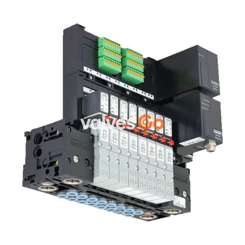
BURKERT 8640 (article 20138859) is a modular 3-bank pneumatic valve block configured with a total width of 33 mm (11 mm width per station) designed for DIN-rail mounting according to EN 50022 (35 x 7.5 mm or 35 x 15 mm). Configured without internal bus communication modules for individual discrete single wiring, this valve assembly integrates a G 1/2 main supply connection (port 1/P) and G 1/4 working service ports (ports 2/A and 4/B) situated opposite the supply side. The block operates within a pressure range of 3.0 to 10.0 bar and handles compressed air or neutral gases from 0 °C to +50 °C under ambient operating temperatures between 0 °C and +55 °C, offering IP20 ingress protection.

Article 20138859 defines a specific modular pneumatic block configuration within the Type 8640 family. The technical parameters reflect factory specifications for discrete control cabinet integration.
| Specification Parameter | Value |
|---|---|
| Product Type | Type 8640 valve block |
| Article Number | 20138859 |
| Configuration | 3-bank (3 valve slots) |
| Width per Station / Total Width | 11 mm per station / 33 mm total assembly width |
| Supply Connection | G 1/2 (port 1/P) |
| Working Connection (Service Ports) | G 1/4 (ports 2/A and 4/B) |
| Working Port Orientation | Opposite of supply side |
| Nominal Operating Pressure | 3.0 bar to 10.0 bar (0.3 MPa to 1.0 MPa) |
| Medium Temperature | 0 °C to +50 °C |
| Ambient Operating Temperature | 0 °C to +55 °C |
| Digital Inputs | 0 PCE |
| Intermediate Feed Modules | 0 PCE |
| Modular Bus Variant | Without (due to single wiring) |
| Internal Bus Communication | Without (due to single wiring) |
| Manual / Automatic Switching | No |
| Integrated Check Valves in Port 3 (R) / 5 (S) | No |
| Pneumatic HotSwap in Port 1 (P) | No |
| Mounting Style | Standard DIN-rail (EN 50022 35 x 7.5 mm or 35 x 15 mm) |
| Ingress Protection Rating | IP20 |
Type 8640 pneumatic valve blocks utilize high-grade polyamide (PA) base bodies and connection modules joined via integrated mechanical snap connectors and latch hooks. O-rings provide sealing across common pneumatic galleries, including supply channel 1 (P) and exhaust channels 3 (R) and 5 (S).
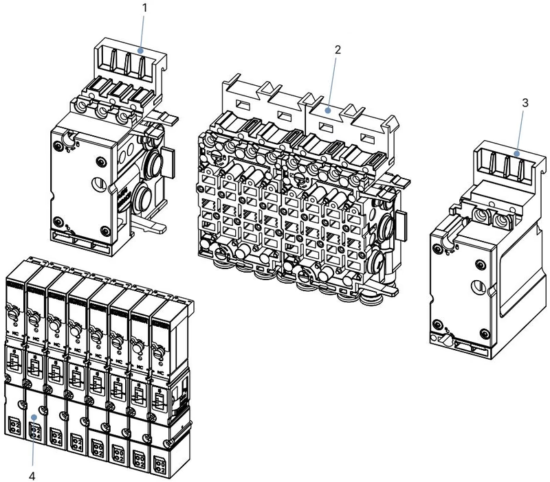
| Item Number | Component Designation |
|---|---|
| 1 | Pneumatic connection module, left |
| 2 | Basic pneumatic modules (11 mm station width) |
| 3 | Pneumatic connection module, right |
| 4 | Pilot solenoid valves (e.g. Type 6524, Type 6525, or Type 0460) |
Sealing Integrity
Pinched, displaced, or missing O-rings and profile seals between modular sub-bases result in internal cross-channel leakage or external pressure drops. Verify complete seal seating prior to latch engagement.
Type 8640 valve blocks with 11 mm station widths host several Bürkert pilot solenoid valve variants:
Pilot valves Type 6524 and 6525 utilize standardized flange interfaces: FM14 or FM20 on REV1/REV2 systems, and FM20 or FM24 on REV3 platforms. Unused valve slots must be sealed with a dedicated pneumatic cover plate (e.g. article 661092) to maintain pneumatic pressure integrity.
BURKERT Type 8640 valve blocks are designed for direct mounting inside standard electrical control cabinets, securing either to standard DIN rails or flat vertical mounting plates.
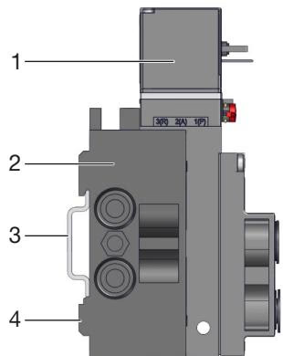
| Item Number | Functional Element |
|---|---|
| 1 | Electrical interface (single wired or modular) |
| 2 | Wall mounting bracket surface |
| 3 | Standard DIN rail (EN 50022 35 x 7.5 mm or 35 x 15 mm) |
| 4 | Pneumatic connection module |
Pneumatic lines must be clean, deburred, and cut square at 90° before insertion into push-in fittings or threaded ports. In accordance with ISO 14743:2020, use hoses with outer diameters conforming to standard tolerances (polyamide PA: 3–10 mm ±0.08 mm, 12–16 mm ±0.1 mm; polyurethane PU: 3–8 mm ±0.1 mm, 10–16 mm ±0.15 mm).
| Port Thread Size | Function / Marking | Recommended Torque | Maximum Tightening Torque |
|---|---|---|---|
| G 1/4 | P, R/S Supply / Exhaust connections | 4.0 to 7.0 Nm | 20 Nm |
| G 1/8 | Service ports A/B, P, R/S connections | 3.0 to 6.0 Nm | 7 Nm |
Pipeline Protection
Do not use solenoid coils as a lever arm when tightening threaded fittings into the connection modules. Install an upstream particulate filter (≤ 5 µm rating) to prevent debris from reaching valve pilot seats.
| Fault Condition | Probable Cause | Corrective Action |
|---|---|---|
| Valves fail to switch | Absence of operating voltage or supply voltage below tolerance | Verify 24 V DC supply across individual conductors; ensure ±10% voltage tolerance. |
| Manual override locked in engaged position | Rotate manual override 90° counterclockwise to return it to the zero position. | |
| Supply pressure below required threshold | Ensure main supply pressure is at least 3.0 bar (pilot operation requires minimum 2.0–3.0 bar). | |
| Delayed switching or exhaust blow-off | System energized before pressure buildup | Apply pneumatic pressure to the manifold before triggering electrical switching commands. |
| Excessive back pressure in exhaust channels | Clean clogged silencers on ports 3 and 5, or install larger expansion exhaust conduits. | |
| External leakage between blocks | Displaced, missing, or crushed internal O-rings | Disassemble sub-modules and install new pre-lubricated seals (e.g. Type MP16 seal set). |
Explore similar products in our catalog


