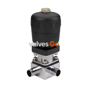
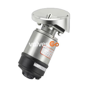
Type 2032

Burkert 341480 Type 2031 2/2-way pneumatically operated diaphragm valve. Features stainless steel body, weld end, EPDM diaphragm, 0-10 bar, -10 to 143 °C.
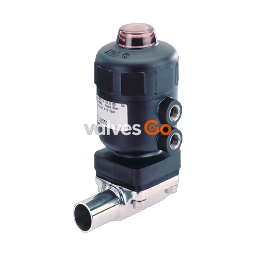
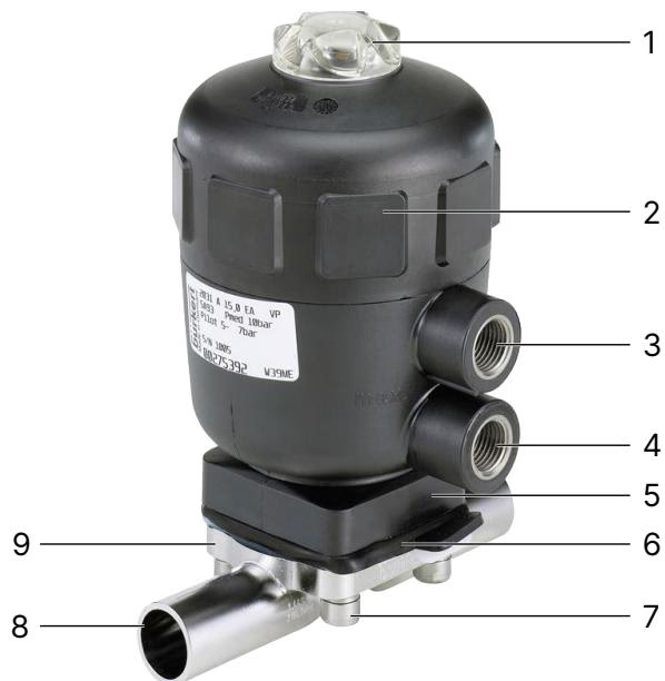
The Burkert Type 2031 (SKU 341480) is an externally controlled 2/2-way diaphragm valve with a pneumatic piston actuator and diaphragm seal. It uses neutral gases or air to control the flow of media. The proven and robust actuator with a stainless steel valve body ensures reliable operation in hygienic or aggressive environments. The flow-optimised valve body with minimal dead space enables high volume flow rates and a wide range of possible applications. The valve is self-draining when in the appropriate installation position.
Depending on the control function, spring force (CF A) or pneumatic pilot pressure (CF B, CF I) generates the closing force. A spindle connected to the actuator piston transfers the force to the compressor, which presses the diaphragm against the weir in the valve body. SKU 341480 is configured with Control Function A (CF A), meaning it is a pneumatically operated 2/2-way on/off valve that is closed by spring force in the rest position.
Ambient temperature:
| Actuator housing material | Actuator size | Permissible ambient temperature [°C] |
|---|---|---|
| PPS | ≤80 (F) | +5...+140 |
| PPS | 100 (G), 125 (H) | +5...+90 (short-term up to +140) |
| PA | ≤125 (H) | -10...+60 |
| PA | ≥175 (K) | -10...+50 |
Medium temperature:
| Valve body material | Permissible medium temperature [°C] |
|---|---|
| Stainless steel | -10...+140 (short-term up to 150) |
Medium temperature for diaphragms: The specified medium temperatures only apply to media that do not attack the diaphragm materials or cause it to swell up. The functional properties and, in particular, the service life of the diaphragm can deteriorate as the medium temperature rises. Do not use the diaphragms as a steam shut-off element.
| Diaphragm material | Medium temperature [°C] | Comments |
|---|---|---|
| EPDM (AD) | -10...+143 | Steam sterilisation max. +150°C for 60 min |
| FKM (FF) | 0...+130 | No steam, dry heat max +150°C for 60 min |
| PTFE (EA) | -10...+130 | Steam sterilisation max. +140°C for 60 min |
| Advanced PTFE (EU) | -5...+143 | Steam sterilisation max. +150°C for 60 min |
| GYLON® (ER) | -5...+130 | Steam sterilisation max. +140°C for 60 min |
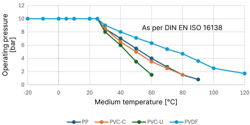
Permissible operating pressure depending on medium temperature in plastic valve body:
INFO
The information in the pressure-temperature diagram is important for material selection. Observe the permissible operating pressure, depending on the medium temperature!
Maximum permissible operating pressure for control function A:
| Diaphragm size | Actuator size | Pilot pressure [bar] | Max operating pressure EPDM, FKM (Dynamic) [bar] | Max operating pressure EPDM, FKM (Static) [bar] | Max operating pressure PTFE (Dynamic) [bar] | Max operating pressure PTFE (Static) [bar] |
|---|---|---|---|---|---|---|
| 6 | 40 (C) | 5.0–7 | 10 | 10 | 10 | 10 |
| 8 | 40 (C) | 5.0–7 | 10 | 10 | 10 | 10 |
| 15 | 50 (D) | 5.0–7 | 8.5 | 10 | - | - |
| 15 | 63 (E) | 5.0–7 | 10 | 10 | 10 | 10 |
| 20 | 63 (E) | 5.5–7 | 10 | 10 | 5 | 10 |
| 20 | 80 (F) | 5.0–7 | 10 | 10 | 10 | 10 |
| 25 | 80 (F) | 5.5–7 | 10 | 10 | 7.5 | 10 |
| 32 | 100 (G) | 5.5–7 | 10 | 10 | 8 | 10 |
| 40 | 100 (G) | 5.5–7 | 6.5 | 10 | 6 | 9 |
| 40 | 125 (H) | 5.5–7 | 10 | 10 | 10 | 10 |
| 50 | 100 (G) | 5.5–7 | 4.5 | 7.5 | 2.5 | 5 |
| 50 | 125 (H) | 5.5–7 | 8 | 10 | 7 | 10 |
| 65 | 125 (H) | 5.5–7 | 7 | 7.5 | 4 | 5 |
| 65 | 175 (K) | 5.0–6 | 8 | 10 | 5 | 6 |
| 80 | 175 (K) | 5.0–6 | 5 | 7 | 3 | 4 |
| 80 | 225 (L) | 5.0–6 | 10 | 10 | 7 | 10 |
| 100 | 225 (L) | 5.0–6 | 8 | 10 | 4 | 7 |
Risk of bursting due to overpressure
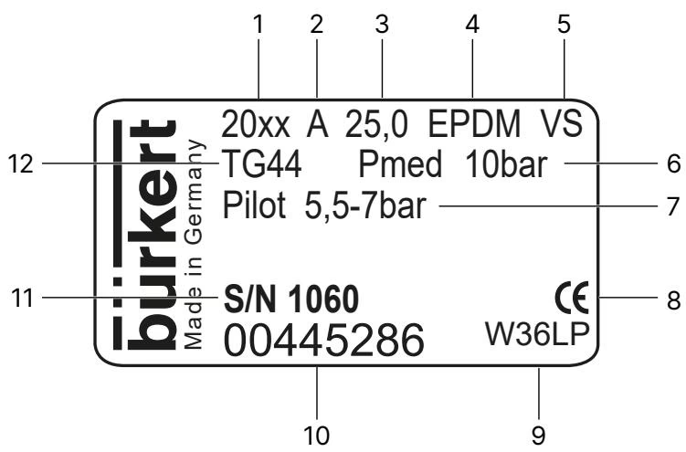
If the device bursts, escaping media may cause injuries, burns or scalds. Do not exceed the maximum permissible pilot pressure or maximum permissible operating pressure. Observe specifications on the type label.
Minimum pilot pressure for control function A:
| Diaphragm size | Actuator size | Minimum pilot pressure [bar] at 0 bar operating pressure | Minimum pilot pressure [bar] at maximum operating pressure |
|---|---|---|---|
| 6 | 40 (C) | 5 | 4 |
| 8 | 40 (C) | 5 | 4 |
| 15 | 50 (D) | 5 | 3.5 |
| 15 | 63 (E) | 5 | 4 |
| 20 | 63 (E) | 5.5 | 4 |
| 20 | 80 (F) | 5 | 4 |
| 25 | 63 (E) | 5 | 4.5 |
| 25 | 80 (F) | 5.5 | 4.5 |
| 32 | 100 (G) | 5.5 | 4 |
| 40 | 100 (G) | 5.5 | 4 |
| 40 | 125 (H) | 5.5 | 4 |
| 50 | 100 (G) | 5.5 | 3.5 |
| 50 | 125 (H) | 5.5 | 3 |
| 65 | 125 (H) | 5.5 | 4.5 |
| 65 | 175 (K) | 6 | 4.5 |
| 80 | 175 (K) | 6 | 5 |
| 80 | 225 (L) | 6 | 5 |
| 100 | 225 (L) | 6 | 5 |
The installer and the operator are responsible for ensuring self-draining. The following points must be observed for optimum self-draining:
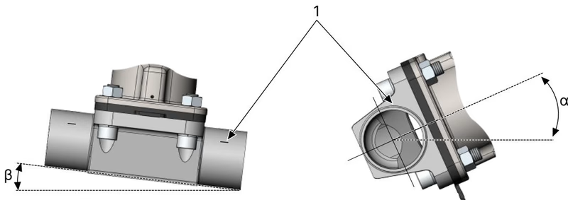
β = Inclination angle of the pipeline, α = Self-draining angle, 1 = Marking for self-draining
Damage to the diaphragm or the actuator
The diaphragm and actuator can be damaged when welding or bonding the valve body into the pipeline. Remove the actuator and diaphragm from the valve body before installation.
Components which are subject to natural wear are seals and the diaphragm. If leaks occur, replace the affected wearing parts with suitable spare parts. The relief bore must be inspected at regular intervals for any medium leakages. A bulging diaphragm may reduce the flow rate.
The service life of the diaphragm depends on the diaphragm material, medium, medium pressure, medium temperature, actuator size, and pilot pressure. To increase the diaphragm service life for CF A, match the actuator size (actuator force) to the medium pressure to be actuated.
Explore similar products in our catalog