Type 2032

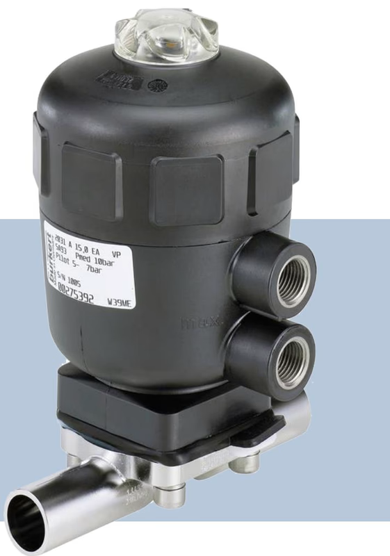
Burkert Type 2031 (SKU 348055) 2/2-way pneumatically operated diaphragm valve. Features a stainless steel body, PA actuator, PTFE/EPDM diaphragm, and weld end connections for hygienic applications.
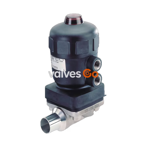
The BURKERT 348055 (Type 2031) is an externally controlled 2/2-way diaphragm valve consisting of a pneumatically operated piston actuator, a diaphragm, and a stainless steel valve body. The proven and robust PA (Polyamide) actuator ensures reliable operation in hygienic or aggressive environments. The flow-optimised valve body with minimal dead space enables high volume flow rates and a wide range of possible applications. This specific model features a weld end connection (DN 15), a PTFE diaphragm with an EPDM backing membrane, and operates with Control Function A (normally closed by spring force). It is designed to handle medium temperatures from -10 °C to 100 °C and operating pressures up to 10 bar.
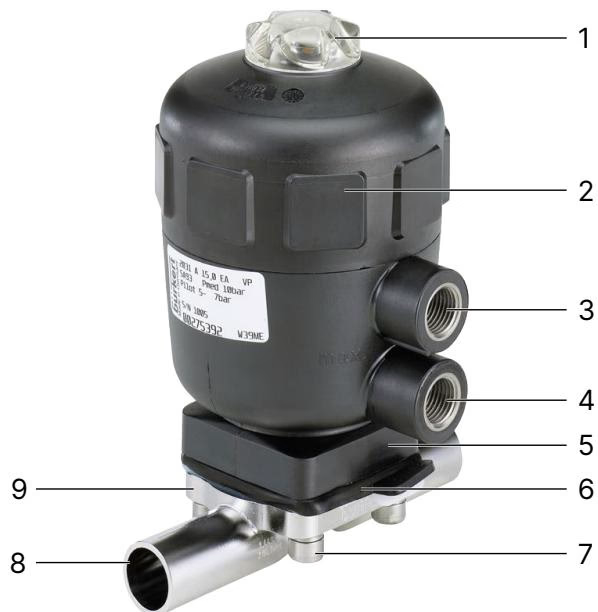
| Item | Description | Item | Description |
|---|---|---|---|
| 1 | Transparent cap with position indicator | 2 | Actuator cover |
| 3 | Upper pilot air port for CF A and CF I | 4 | Lower pilot air port for CF A and CF I |
| 5 | Diaphragm bonnet | 6 | Diaphragm |
| 7 | Body screw | 8 | Port connection |
| 9 | Valve body |
Ambient Temperature
| Actuator housing material | Actuator size | Permissible ambient temperature [°C] |
|---|---|---|
| PA | ≤125 (H) | -10...+60 |
| PA | ≥175 (K) | -10...+50 |
Medium Temperature for Diaphragms
The specified medium temperatures only apply to media that do not attack the diaphragm materials or cause it to swell up. The functional properties and, in particular, the service life of the diaphragm can deteriorate as the medium temperature rises. Do not use the diaphragms as a steam shut-off element.
| Diaphragm material | Medium temperature [°C] | Comments |
|---|---|---|
| PTFE (EA) | -10...+130 | Steam sterilisation max. +140°C for 60 min |
Risk of bursting due to overpressure
If the device bursts, escaping media may cause injuries, burns or scalds. Do not exceed the maximum permissible pilot pressure or maximum permissible operating pressure. Observe the permissible ambient temperature and medium temperature.
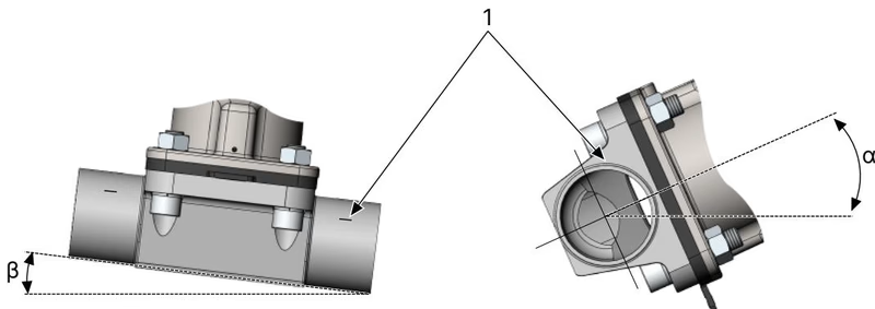
The installer and the operator are responsible for ensuring self-draining. The following points must be observed for optimum self-draining:
Damage to the diaphragm or the actuator
The diaphragm and actuator can be damaged when welding or bonding the valve body into the pipeline. Remove the actuator and diaphragm from the valve body before installation.
Risk of crushing
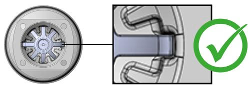
If the compressor is not positioned correctly and the actuator is actuated, this may result in injuries and damage to the device. Before actuating the actuator, ensure that the compressor is in the correct position.
Risk of injury from sudden discharge of pressure and escaping medium
Disassembling a pressurised device can cause medium to escape unexpectedly or a sudden discharge of pressure. Before disassembly, shut off the pressure and vent all lines. Completely drain the lines.
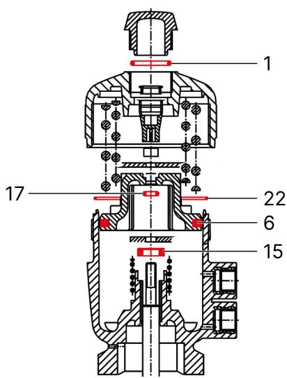
| Item | Description | Item | Description |
|---|---|---|---|
| 1 | O-Ring | 15 | Lip seal |
| 6 | Piston seal | 17 | O-Ring |
| 22 | O-Ring |
Risk of injury when unscrewing the transparent cap
If the transparent cap is pressurised when it is unscrewed, it can cause serious injuries due to high force and speed and an uncontrolled trajectory. Before unscrewing the transparent cap, ensure that the upper piston chamber is depressurised.
Explore similar products in our catalog