

PN16

Burkert 351905 Type 6013 direct-acting 2/2-way plunger solenoid valve. Features 1.5mm orifice, 0-16 bar pressure range, brass body, and ATEX/IECEx certification.
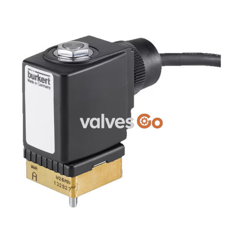
Burkert 351905 Type 6013 is a direct-acting 2/2-way plunger solenoid valve designed for reliable fluid control. The stopper and the core guide tube are welded together to increase pressure resistance and leak-tightness. A variety of seal material combinations are available to suit different applications. A Bürkert-specific flange variant (SFB) enables the space-saving arrangement of valves on a multiple manifold. The 351905 model specifically features a 1.5 mm orifice, brass body, NBR seal, and an ATEX/IECEx approved wire cable connection for hazardous locations.
| Product Properties | Specification |
|---|---|
| Dimensions | See Dimensions section |
| Seal Material | FKM, PTFE/Graphite (EPDM/NBR on request/specific models) |
| Body Material | Brass, stainless steel 1.4305/303 |
| Coil Material | Polyamide, epoxy |
| Orifice | DN 2.0 to DN 6.0 (1.5 mm for model 351905) |
| Circuit Function | A (Normally closed) and B (Normally open) |
| Thermal Insulation Class | Polyamide coil class B, Epoxy coil class H |
| Duty Cycle | 100% continuous operation; Intermittent operation 60% (30 min) or with 5 W coil |
| Operating Voltage | 24 V DC, 24 V 50 Hz, 24 V 60 Hz, 120 V 50 Hz, 230 V 50 Hz, 240 V 60 Hz |
| Voltage Tolerance | ±10% |
| Operating Medium | Technical vacuum, neutral gases and liquids (e.g., compressed air, water, hydraulic oil) |
| Medium Temperature (FKM) | -10 °C to +100 °C (PA coil), -10 °C to +120 °C (Epoxy coil) |
| Viscosity | Max. 21 mm²/s |
| Electrical Connection | ATEX/IECEx variant with 3 m moulded cable or terminal cable; Plug contacts according to DIN EN 175301-803 form A |
| Port Connection | G 1/8, G 1/4, G 3/8, NPT 1/8, NPT 1/4, NPT 3/8, manifold (SFB) |
| Degree of Protection | IP65 with cable plug |
| Installation Position | As required, preferably with actuator upright |
| Ambient Temperature | Max. +55 °C |
| Symbol | Description |
|---|---|
| CF A | 2/2-way solenoid valve, Direct-acting, Normally closed |
| CF B | 2/2-way solenoid valve, Direct-acting, Normally open |
Conformity Notes
The approvals and conformities listed below must be stated when making enquiries. Not all available variants can be supplied with all mentioned approvals.
Explosion Protection Optional explosion protection according to category 2 (zone 1/21) or category 3 (zone 2/22) is available.
North America (USA/Canada)
Drinking Water & Hygiene
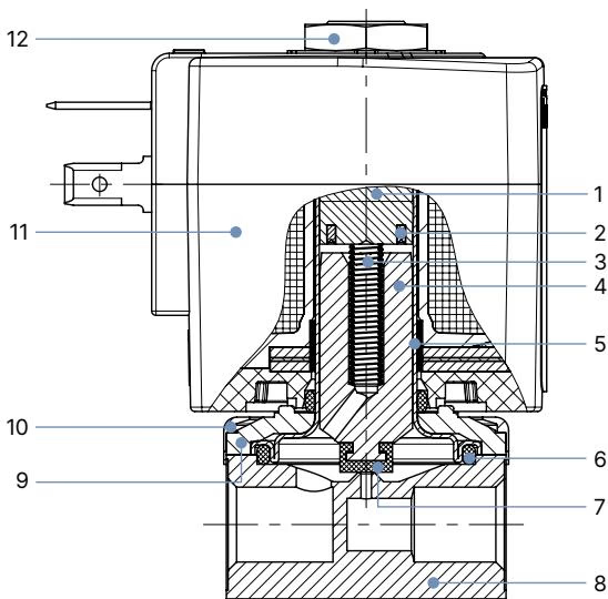
| No. | Element | Material |
|---|---|---|
| 1 | Stopper | Stainless steel 1.4105/430F |
| 2 | Shading ring | Cu (brass variant), Ag (stainless steel variant) |
| 3 | Spring | Stainless steel 1.4310/301 |
| 4 | Magnetic core | Stainless steel 1.4105/430F |
| 5 | Core guide tube | Stainless steel 1.4303/305/308 |
| 6 | Seal | FKM, Graphite (high temperature variant) |
| 7 | Armature seal | FKM, PTFE |
| 8 | Valve body | Brass, Stainless steel 1.4305/303 |
| 9 | Sub-base | Steel, surface finish thick-film passivated (brass variant); Stainless steel 1.4301/304 (stainless steel variant) |
| 10 | Cover | Polyamide |
| 11 | Coil | PA (polyamide), Epoxy |
| 12 | Nut | Steel, surface finish thick-film passivated (brass variant); Stainless steel 1.4305/303 PTFE coated (stainless steel variant) |
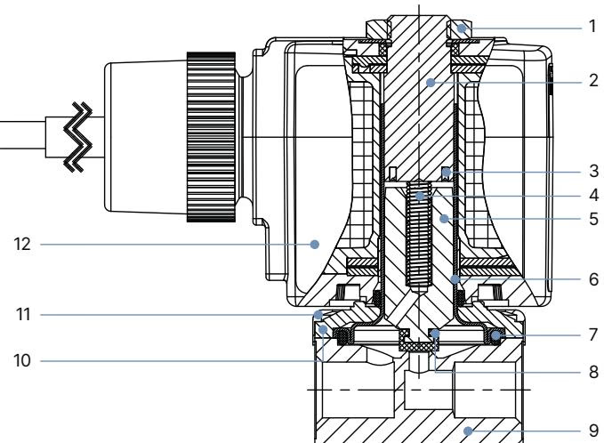
| No. | Element | Material |
|---|---|---|
| 1 | Nut | Steel (brass variant), Stainless steel 1.4305/303 PTFE coated (stainless steel variant) |
| 2 | Stopper | Stainless steel 1.4105/430F |
| 3 | Shading ring | Cu (brass variant), Ag (stainless steel variant) |
| 4 | Spring | Stainless steel 1.4310/301 |
| 5 | Magnetic core | Stainless steel 1.4105/430F |
| 6 | Core guide tube | Stainless steel 1.4303/305/308 |
| 7 | Seal | FKM, Graphite (high temperature variant) |
| 8 | Armature seal | FKM, PTFE (high temperature variant) |
| 9 | Valve body | Brass, Stainless steel 1.4305/303 |
| 10 | Sub-base | Steel (brass variant), Stainless steel 1.4301/304 (stainless steel variant) |
| 11 | Cover | Polyamide |
| 12 | Coil | Epoxy |
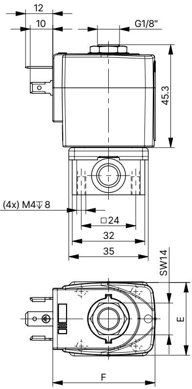
| Port connection | A [inch] | B [mm] | C [mm] | D [mm] | G [mm] |
|---|---|---|---|---|---|
| Thread | G/NPT 1/8 | 32 | 20.8 | 32.6 | 8 |
| Thread | G/NPT 1/4 | 46 | 26.8 | 49 | 12 |
| Thread | G/NPT 3/8 | 50 | 39.8 | 38 | 12 |
| Flange | - | 32 | 14.3 | 32.6 | - |
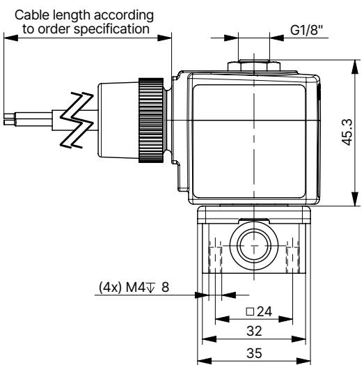
| Port connection | A [inch] | B [mm] | C [mm] | D [mm] | G [mm] |
|---|---|---|---|---|---|
| Thread | G/NPT 1/8 | 32 | 20.8 | 32.6 | 8 |
| Thread | G/NPT 1/4 | 46 | 26.8 | 49 | 12 |
| Thread | G/NPT 3/8 | 50 | 39.8 | 38 | 12 |
| Flange | - | 32 | 14.3 | 32.6 | - |
Power Consumption (Circuit Function A)
| Orifice [mm] | Power consumption | Inrush AC [VA] | Hold AC [VA] | Opening [ms] | Closing [ms] |
|---|---|---|---|---|---|
| 2.0 | 8 W AC or 8 W DC | 24 | 17 | 20 | 30 |
| 2.5 | 8 W AC or 8 W DC | 24 | 17 | 20 | 30 |
| 3.0 | 8 W AC or 8 W DC | 24 | 17 | 20 | 30 |
| 4.0 | 8 W AC or 8 W DC | 24 | 17 | 20 | 30 |
| 6.0 | 8 W AC or 8 W DC | 24 | 17 | 20 | 30 |
Explosion Hazard
The device is a closed system. Do not dismantle it. In potentially explosive areas, the surface of the device must only be cleaned with a damp or anti-static cloth to prevent electrostatic charges.
Installation Position
The valve can be installed in any position, but it is recommended to install it with the actuator upright.
Explore similar products in our catalog


