


Up to 99.8% Efficiency

BURKERT 363215 (Type 3361) electromotive 2-way globe control valve features G 3/8 stainless steel CF3M body, AG2 electric actuator with 6 mm/s travel speed, 24 V DC supply, and 0 to 25 bar operating pressure.
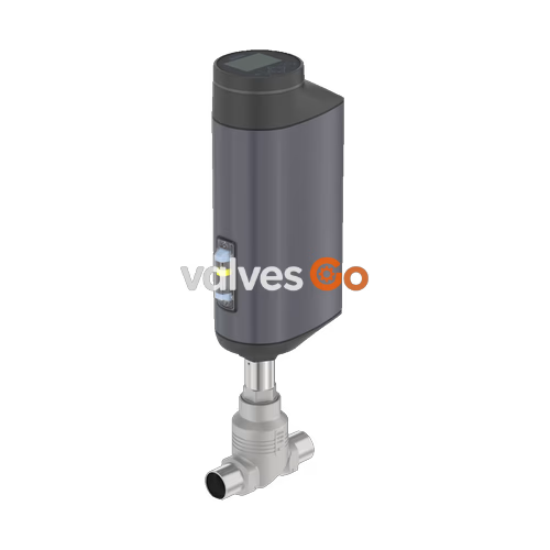
BURKERT 363215 (Type 3361) is an electromotive 2-way globe control valve engineered for precise dynamic regulation in demanding industrial continuous processes. The specific unit configuration combines a G 3/8" female threaded valve body in investment cast stainless steel CF3M with an AG2 electromotive linear actuator powered by 24 V DC. Actuator linear thrust is generated via an electric brushless DC motor and precision ball screw, delivering a constant travel speed of 6 mm/s under a nominal actuator force of 1,300 N. This mechanical coupling eliminates dead-band displacement caused by fluctuating media inlet pressures, holding valve positions rigidly with a control dead band within ±0.1%.
Flow passes through the valve body below the seat (direction 2 to 1), opposing the plug closure direction to prevent water hammer and pressure shocks. The Type 3361 modular platform permits interchangeable valve seats across five distinct seat diameters for each port connection. For the DN 10 (G 3/8") port connection, seat sizes ranging from 3 mm to 10 mm provide calibrated Kvs ratings from 0.1 m³/h to 2.7 m³/h with theoretical rangeabilities reaching up to 50:1. Operating pressures range from 0 to 25 bar(g), and the enclosure is sealed to IP65/IP67 and NEMA 4X standards.
| Specification Parameter | Value / Technical Rating |
|---|---|
| Manufacturer Model Number | 363215 |
| Type Series | 3361 |
| Valve Construction | 2-way globe control valve with linear electric actuator |
| Actuator Size | AG2 (Actuator size 2, nominal force 1,300 N) |
| Port Connection Size | DN 10 / NPS 3/8" (female thread G 3/8 DIN ISO 228-1) |
| Body Pressure Rating | PN 25 (DIN EN 1333) / Class 150 (DIN EN 1759) |
| Operating Pressure Range | 0 to 25 bar(g) (vacuum version down to -0.9 bar(g) optional) |
| Fluid Temperature Range | -40 °C to +230 °C (depending on seat seal material) |
| Ambient Temperature Range | -25 °C to +65 °C (without expansion modules; subject to derating) |
| Maximum Media Viscosity | Up to 600 mm²/s |
| Control Characteristic | Equal-percentage (linear available on request) |
| Actuator Travel Speed | 6 mm/s (for 1,300 N nominal force) |
| Closing Time | 3.3 s to 6.6 s (depending on stroke travel and operating limits) |
| Position Control Dead Band | ±0.1% |
| Operating Supply Voltage | 24 V DC ± 10% (maximum permissible residual ripple 10%) |
| Maximum Current Consumption | 3 A (full load including 1 A SAFEPOS charging current; +2 A at lowest temp) |
| Standby Power Draw | 2 W to 5 W |
| Operating Duty Cycle | 100% continuous duty |
| Protection Class (DIN EN 61140) | Class III |
| Enclosure Ingress Protection | IP65 / IP67 (DIN EN 60529), NEMA 4X |
| Actuator Weight | 5.5 kg (AG2 actuator head alone, excluding body) |
| Approved Operating Media | Steam, neutral gases, water, alcohols, oils, fuels, hydraulic fluids, salt solutions, organic solvents |
Type 3361 utilizes non-corrosive materials designed for hygiene, washdown resistance, and durability under mechanical vibration.
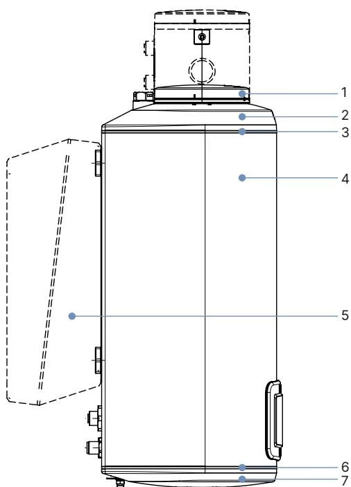
| Item | Component Description | Material Specification |
|---|---|---|
| 1 | Display housing / Blind cover / Gateway cover | PPS (Standard); Stainless steel 1.4301 (ATEX/IECEx variants) |
| 2 | Actuator upper cover | PPS |
| 3 | Static housing seals | EPDM |
| 4 | Actuator main housing body | Powder-coated cast aluminium |
| 6 | Base sealing gaskets | EPDM |
| 7 | Actuator base flange | PPS |
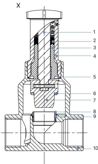
| Item | Component Description | Material Specification |
|---|---|---|
| 1 | Valve spindle (stem) | Stainless steel 1.4401 (316) / 1.4404 (316L) |
| 2 | Spindle gland packing | PTFE V-rings (filled) with stainless spring compensation |
| 3 | Spindle guide bush | Stainless steel 1.4404 (316L) |
| 4 | Packing gland tube | Stainless steel 1.4401 (316) |
| 5 | Body-to-bonnet gasket | Graphite or PTFE |
| 6 | Seat sealing insert | Stainless steel 1.4571, PTFE, or PEEK washer |
| 7 | Control cone (plug) | Stainless steel 1.4571 (optionally hardened) |
| 8 | Replaceable valve seat | Stainless steel 1.4571 (optionally hardened) |
| 9 | Seat O-ring (seat size ≥ 25) | EPDM or PTFE |
| 10 | Valve body | Stainless steel CF3M (cast 316L equivalent) |
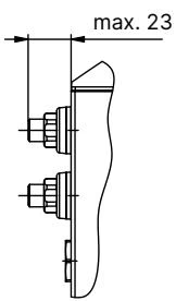
Actuator heights are defined from the pipeline centerline to the top edge of the cover. In the closed seated position without tight shut-off preload, the actuator rises approximately 2 mm.
| Nominal Diameter DN | Nominal Pipe Size NPS | Height H1 (Standard Variant) [mm] | Height H2 (Fieldbus Variant) [mm] |
|---|---|---|---|
| 10 | 3/8" | 417 | 489 |
| 15 | 1/2" | 417 | 489 |
| 20 | 3/4" | 423 | 495 |
| 25 | 1" | 446 | 518 |
| 32 | 1 1/4" | 474 | 546 |
| 40 | 1 1/2" | 479 | 551 |
| 50 | 2" | 485 | 557 |
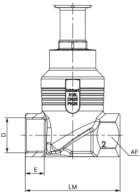
| DN | NPS | Thread D | Thread Depth E [mm] | Face-to-Face LM [mm] | Hexagon Wrench Flat AF [mm] |
|---|---|---|---|---|---|
| 10 | 3/8" | G 3/8 | 12.0 | 65 | 27 |
| 15 | 1/2" | G 1/2 | 14.0 | 65 | 27 |
| 20 | 3/4" | G 3/4 | 16.0 | 75 | 34 |
| 25 | 1" | G 1 | 18.0 | 90 | 41 |
| 32 | 1 1/4" | G 1 1/4 | 20.0 | 110 | 50 |
| 40 | 1 1/2" | G 1 1/2 | 22.0 | 120 | 55 |
| 50 | 2" | G 2 | 24.0 | 150 | 70 |
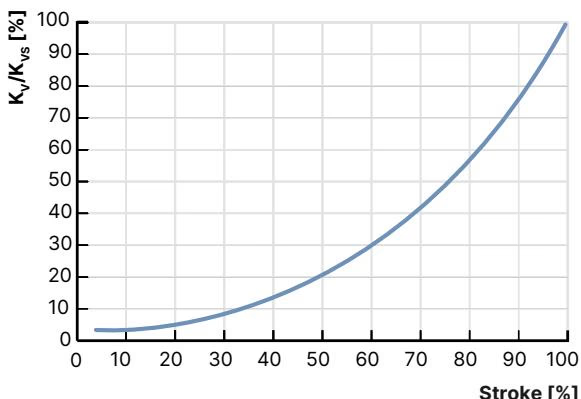
The standard control trim produces an equal-percentage flow characteristic in compliance with DIN EN 60534-2-4. Water flow test measurements determine intermediate Kv figures as a function of percentage stroke travel.
| Seat Size [mm] | Actuator Force [N] | Max Operating Pressure Stainless [bar(g)] | Max Operating Pressure PTFE [bar(g)] | Max Operating Pressure PEEK [bar(g)] | Rangeability | Kv 10% [m³/h] | Kv 30% [m³/h] | Kv 50% [m³/h] | Kv 70% [m³/h] | Kv 90% [m³/h] | Kvs 100% [m³/h] |
|---|---|---|---|---|---|---|---|---|---|---|---|
| 3 | 1,300 | 25 (Class IV) | — | — | 20:1 | 0.005 | 0.013 | 0.026 | 0.044 | 0.077 | 0.10 |
| 3 | 1,300 | 25 (Class IV) | — | — | 20:1 | 0.009 | 0.023 | 0.046 | 0.085 | 0.160 | 0.20 |
| 4 | 1,300 | 25 (Class IV) | — | — | 30:1 | 0.023 | 0.049 | 0.097 | 0.180 | 0.350 | 0.50 |
| 6 | 1,300 | 25 (Class VI) | 25 (Class VI) | — | 50:1 | 0.007 | 0.045 | 0.160 | 0.410 | 1.100 | 1.25 |
| 8 | 1,300 | 25 (Class VI) | 25 (Class VI) | — | 50:1 | 0.070 | 0.120 | 0.260 | 0.610 | 1.500 | 2.00 |
| 10 | 1,300 | 25 (Class VI) | 25 (Class VI) | — | 50:1 | 0.110 | 0.190 | 0.480 | 1.000 | 2.300 | 2.70 |
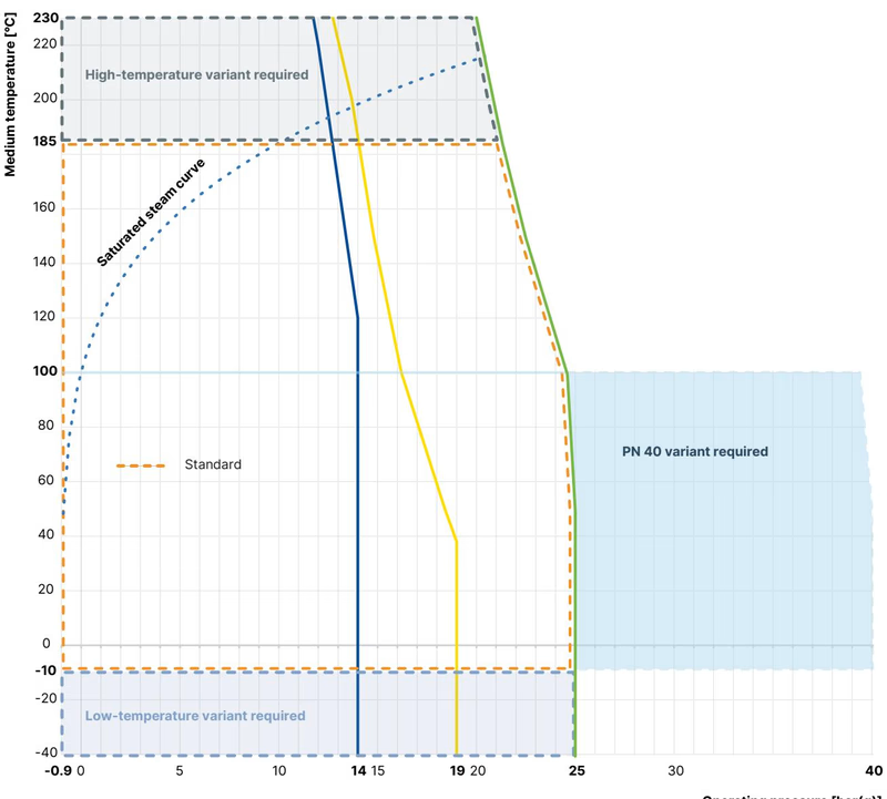
Fluid pressure retention and actuator electronics operating limits interact directly based on process media temperatures.
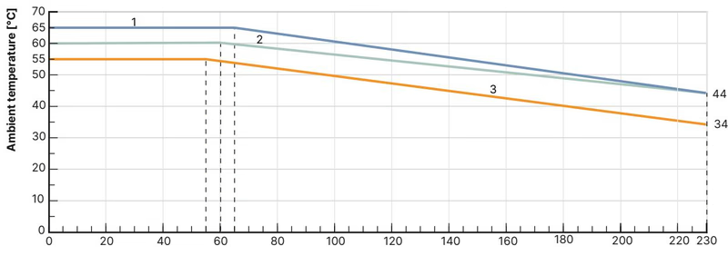
In the AG2 ambient temperature chart above, curve 1 applies to basic units without modules, curve 2 applies to units with an illuminated display module, and curve 3 applies to units equipped with the SAFEPOS energy-pack or integrated fieldbus gateway.
| Tight Shut-off | Leakage Class (DIN EN 60534-4) | Permissible Media Temperature | Seat Material Selection |
|---|---|---|---|
| Not required | Class III / IV (Metal-to-metal) | -40 °C to +230 °C | Stainless steel 1.4571 (Permissible leakage 0.1% or 0.01% of nominal flow) |
| Not required | Class III / IV (Hardened metal) | -40 °C to +230 °C | Hardened stainless steel (Recommended for wet steam, cavitation, or abrasive media) |
| Required | Class VI (Soft seal bubble-tight) | -40 °C to +130 °C | PTFE seal washer (Recommended for process temperatures ≤ +130 °C) |
| Required | Class VI (Soft seal bubble-tight) | -10 °C to +230 °C | PEEK seal washer (Recommended for process temperatures > +130 °C) |
Special Application Variants
Special product executions supported by the Type 3361 platform include:
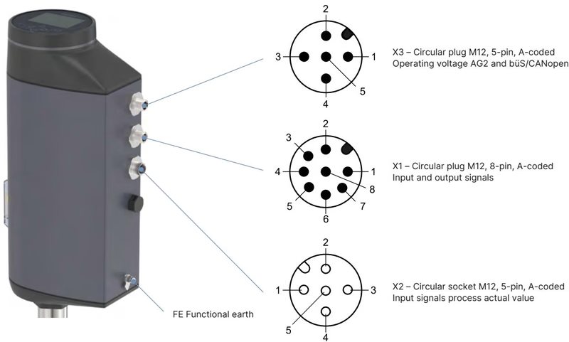
The AG2 actuator is supplied with either an internal 3x M20 cable gland terminal strip or standard M12 circular industrial connectors.
| Pin Number | Signal Assignment |
|---|---|
| 1 | Digital input + |
| 2 | GND for digital input and digital outputs |
| 3 | Digital output 2 + (PNP, max. 100 mA) |
| 4 | Digital output 1 + (PNP, max. 100 mA) |
| 5 | Analogue output - |
| 6 | Analogue output + (0/4–20 mA or 0–5/10 V) |
| 7 | Set-point value / Analogue input - |
| 8 | Set-point value / Analogue input + (0/4–20 mA or 0–5/10 V) |
| Pin Number | Signal Assignment |
|---|---|
| 1 | CAN Shield / Cable shield |
| 2 | Operating voltage 24 V DC ± 10% |
| 3 | GND / CAN_GND |
| 4 | CAN_H |
| 5 | CAN_L |
| Pin Number | 4–20 mA Sensor Input (Externally Supplied) |
|---|---|
| 1 | Do not connect |
| 2 | Do not connect |
| 3 | Do not connect |
| 4 | Process actual value 4–20 mA (input resistance 80 Ω, 12 bit) |
| 5 | Process actual value GND |
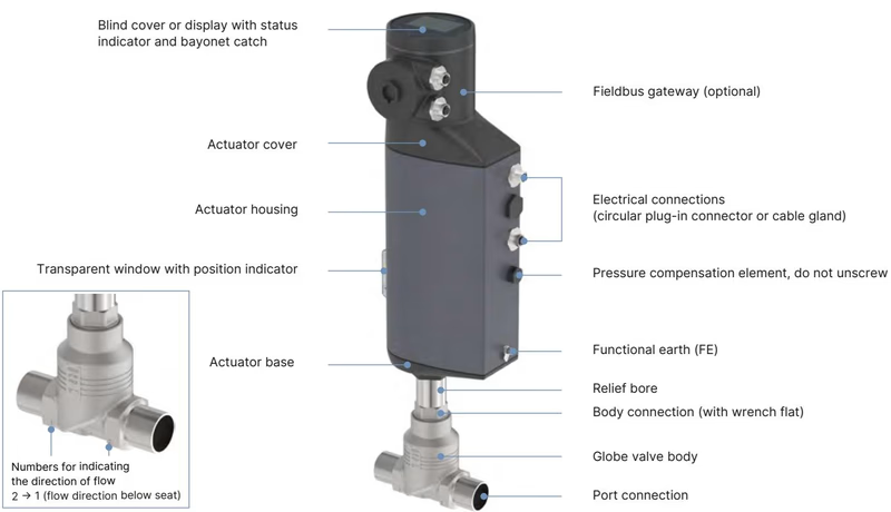
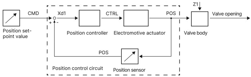
The internal microprocessor compares the target set-point (CMD) with the real-time position sensor feedback (POS). If a control deviation (Xd1) occurs, the brushless DC motor repositions the valve cone via the actuating variable CTRL. An optical 360° LED ring indicates operating states, end-position limits, warnings, and device diagnostics through customizable colour and flash patterns.
Manual Override Operation
When electrical power is connected, the valve can be actuated electrically in MANUAL mode using the push buttons located beneath the blind cover or via display keys. When power is off, mechanical manual actuation is available:
Maintenance and rebuild procedures require dedicated assembly torques and approved chemical lubricants.
| Joint / Threaded Component | Port Size DN | Tightening Torque [Nm] | Tightening Torque [lbf·ft] |
|---|---|---|---|
| Body Connection to Actuator Base | DN 10 / 15 | 45 ± 3 | 33 ± 2 |
| Body Connection to Actuator Base | DN 20 | 50 ± 3 | 37 ± 2 |
| Body Connection to Actuator Base | DN 25 | 60 ± 3 | 44 ± 2 |
| Replaceable Valve Seat Thread | DN 10 / 15 (Seat sizes 3–15) | 20 (+3 / -0) | 15 (+2 / -0) |
| Packing Gland Spindle Guide Bush | DN 10 / 15 (Spindle ø 10 mm) | 15 | 11 |
| Actuator Base Housing Screws | AG2 (4x housing screws) | 5.0 | 3.7 |
| Gateway Fastening Screw | M12 Gateway / Bayonet | 1.1 | 0.8 |
| SAFEPOS Bracket Retaining Screw | T10 Torx locking screw | 1.1 | 0.8 |
All body connection threads, spindle guide threads, and seat installation threads must be lubricated using food-grade lubricant Klüberpaste UH1 96-402 (or OKS 1110-3 silicone grease for static seals). For oxygen service, only BAM-approved oxygen lubricants may be applied.
Position Calibration via X.TUNE
After remounting the actuator, replacing the control cone, exchanging the valve seat, or renewing the packing gland, the position controller must be recalibrated by running the X.TUNE function:
Original replacement parts ensure process reliability, seat tightness, and extended valve operating lifecycles.
| Component Description | Port Size / Sub-assembly | Order Article Number |
|---|---|---|
| Control Cone Set (Steel/Steel) | DN 10/15, Seat Size 4 | 149 934 |
| Control Cone Set (Steel/Steel) | DN 10/15, Seat Size 6 | 152 696 |
| Control Cone Set (Steel/Steel) | DN 10/15, Seat Size 8 | 149 935 |
| Control Cone Set (Steel/Steel) | DN 10/15, Seat Size 10 | 149 912 |
| Replacement Valve Seat Set | DN 10/15, Seat Size 3 | 284 777 |
| Replacement Valve Seat Set | DN 10/15, Seat Size 4 | 262 143 |
| Replacement Valve Seat Set | DN 10/15, Seat Size 6 | 262 146 |
| Replacement Valve Seat Set | DN 10/15, Seat Size 8 | 262 147 |
| Replacement Valve Seat Set | DN 10/15, Seat Size 10 | 262 149 |
| Packing Gland Seal Set | Spindle ø 10 mm, DN 10–20 | 285 685 |
| Stainless Spindle Guide Bush | Body DN 10/15, Spindle ø 10 mm | 246 577 |
| Valve Seat Installation Tool | DN 15/10 Seat Replacement | 652 604 |
| Modified Socket Wrench SW19 | Packing Gland Spindle ø 10 mm | 683 220 |
| SAFEPOS Energy-Pack Storage Unit | AG2 Actuator (Wear Part) | 285 834 |
| Plastic Dummy Cover | AG2 / AG3 Actuator Enclosure | 277 881 |
| M12 Power Cable 5 m (Socket, 4-pin) | AG2 Power X3 (Without Comm.) | 918 038 |
| M12 Signal Cable 2 m (Socket, 8-pin) | AG2 I/O Signals X1 | 919 061 |
| USB büS Interface Set 1 | PC Diagnostic Stick Set Type 8923 | 772 426 |
Explore similar products in our catalog


