

PN16

Burkert 363967 (Type 8640) is a 14-bank modular pneumatic valve block with 19 mm station width, G 1/4 pressure ports, and D6 push-in working ports. Rated 2 to 8 bar with single wiring and DIN rail mounting.
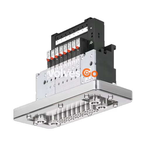
BURKERT 363967 Type 8640 is a 14-bank modular pneumatic valve block configured with a 19 mm station width for Type 5470 solenoid pilot valves. Built on polyamide (PA) modular base blocks, this pneumatic assembly integrates a G 1/4 central pressure port and D6 push-in working ports positioned opposite the supply side. Operating across a nominal pressure range of 2.0 to 8.0 bar, the unit is engineered for direct DIN rail mounting in industrial control systems.
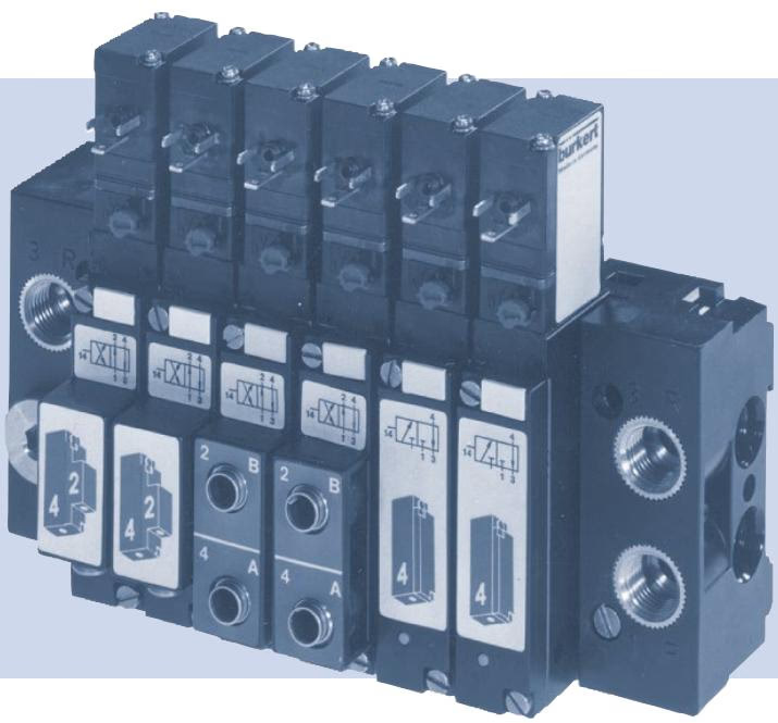
This specific configuration functions without an internal bus communication interface, utilizing individual wiring for each valve position. It handles neutral gaseous media and compressed air within a medium temperature window of 0 °C to 50 °C and ambient temperatures from 0 °C to 55 °C, delivering an ingress protection level of IP20.
| Specification Parameter | Value |
|---|---|
| Product Type | Type 8640 modular valve block |
| Article Number (SKU) | 363967 |
| Number of Valve Stations | 14-bank |
| Width per Station | 19.00 mm |
| Pressure Supply Port 1 (P) | G 1/4 |
| Working Ports 2 and 4 | D6 push-in connectors |
| Working Connection Position | Opposite supply side |
| Nominal Pressure Range | 2.00 bar to 8.00 bar |
| Flow Rate Medium Temperature | 0.00 °C to 50.00 °C |
| Operating Ambient Temperature | 0.00 °C to 55.00 °C |
| Operating Medium | Filtered compressed air (particle size max. 10 μm), unlubricated or lubricated; neutral gases (5 μm filter) |
| Compressed Air Quality | ISO 8573-1:2010, Class 7.4.4 |
| Nominal Operating Mode | Continuous operation (100% duty cycle) |
| Ingress Protection Class | IP20 (IP65 achievable with Type 2516 cable plug) |
| Mounting Execution | Standard rail installation (DIN EN 50022 35 x 7.5 or 35 x 15) |
| Communication / Bus System | Without internal bus communication (single wiring) |
| Intermediate Feed Modules | 0 PCE |
| Integrated Check Valves | No (in ports 3 [R] and 5 [S]) |
| Pneumatic HotSwap in Port 1 | No |
The Type 8640 19 mm pneumatic block is populated with Type 5470 pilot-operated valves. Each valve body is manufactured from polyamide (PA) with NBR elastomer seals and DN 4.0 mm nominal orifices, actuated by a Type 6106 rocker solenoid pilot mechanism. The armature pivots on a tilting bearing, which eliminates sliding friction, prevents mechanical wear, and operates without baseline lubrication.
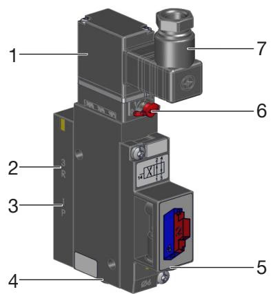
| Item | Designation | Item | Designation |
|---|---|---|---|
| 1 | Pilot valve Type 6106 | 5 | Working port 2 |
| 2 | Exhaust port 3 | 6 | Manual override |
| 3 | Pressure port 1 | 7 | Cable plug Type 2506 / Type 2516 |
| 4 | Working port 4 | — | — |
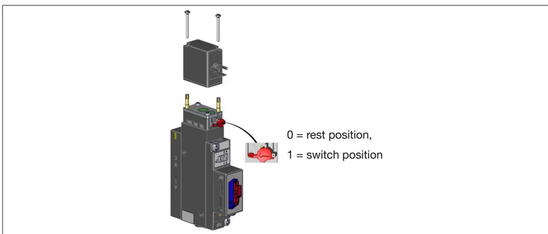
Each valve station includes a mechanical manual override for commissioning and service testing. Actuation is achieved by pressing the override actuator and rotating it 90° clockwise until it hits the internal mechanical stop. The override locks in position without self-resetting.
Manual Override Operation
Operate the manual override only when electrical power is switched off. The manual override must be turned back to the zero position and unlocked prior to resuming electrical control.
Type 5470 4/2-way valves can be mechanically configured to function as 3/2-way valves by blanking off individual service ports with a dedicated sealing stopper:
Operating Reliability in Continuous Duty
If continuous operation is interrupted for extended periods, perform 1 to 2 switching cycles per day throughout the downtime to maintain functional switching reliability.
Type 8640 valve blocks are constructed from modular multi-block segments that lock mechanically via integrated latch hooks and tabs, sealed pneumatically by dual NBR O-rings between adjacent modules.
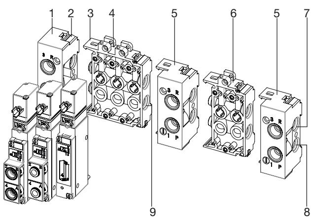
Assembly sequence for pneumatic base modules:
Sealing Integrity
Crushed, pinched, or missing O-rings and profile seals between modular blocks cause pressure leakage. Confirm exact O-ring alignment before snapping modules together or fastening valves.
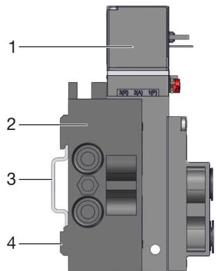
The assembled 14-bank block can be secured onto standard DIN EN 50022 rails (35 x 7.5 mm or 35 x 15 mm) or mounted directly to a flat panel wall:
| Port Size | Thread Function | Recommended Torque | Maximum Permissible Torque |
|---|---|---|---|
| G 1/4 (NPT 1/4) | Supply 1 (P), Exhaust 3 (R) | 4 to 7 Nm | 20 Nm |
| G 1/8 (NPT 1/8) | Outlets 2 (B), 4 (A) | 3 to 6 Nm | 7 Nm |
Pneumatic piping requires clean, calibrated tubing with a minimum hardness of 40 Shore D conforming to DIN 53505 / ISO 868 and outer diameter dimensional tolerances per DIN 73378 (±0.1 mm maximum deviation).
Cut hoses square without burrs and insert them firmly into the D6 push-in connectors until they bottom out against the internal retention claws. Minimum tensile holding forces per DIN ISO 14743:2020 must be observed during mechanical pull checks:
| Tube Outer Diameter (OD) | 3 mm | 4 mm | 6 mm | 8 mm | 10 mm | 12 mm | 16 mm |
|---|---|---|---|---|---|---|---|
| Polyamide (PA) Min. Tensile Force | 60 N | 70 N | 120 N | 170 N | 250 N | 300 N | 350 N |
| Polyurethane (PU) Min. Tensile Force | 25 N | 50 N | 100 N | 150 N | 200 N | 200 N | 300 N |
Electrical Safety
Disconnect all operating voltages before servicing the electrical components. Ensure the protective conductor is connected and continuity exists between coil ground and valve housing (maximum resistance 0.1 Ω tested at 12 V / 1 A).
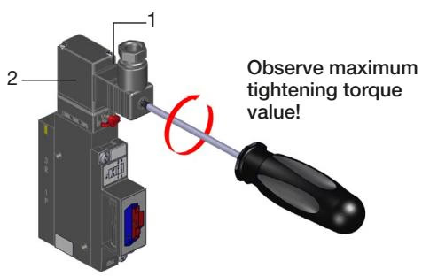
Single wiring connections interface via DIN EN 175301-803 Form C cable plugs (such as Burkert Type 2516). Fasten the cable plug retention screw to a torque of 0.3 Nm, confirming that the elastomeric flat gasket is seated evenly to maintain IP65 integrity at the coil level.
| Fault Condition | Probable Cause | Corrective Action |
|---|---|---|
| Valves fail to switch | Missing or insufficient electrical supply voltage | Verify line voltage against type label specifications; inspect wiring terminals. |
| Manual override locked in engaged position | Return manual override to zero position. | |
| Supply pressure missing or below operating threshold | Restore supply air volume; ensure line pressure is ≥ 2.0 bar (minimum 70% of operating pressure). | |
| Valves switch sluggishly or exhaust continuously | Inadequate line pressure or restricted flow capacity | Verify upstream regulators, filters, and valves; maintain supply pressure ≥ 2.0 bar. |
| Block pressurized while valves were energized | De-energize all coils prior to building system line pressure. | |
| Exhaust silencer blocked by debris | Clean exhaust silencers or replace with unrestricted larger expansion units. | |
| Particulate contamination inside valve pilot seat | Blow out exhaust passages with pressure pulses or replace contaminated pilot valve. | |
| Air leakage across valve block | Damaged or missing O-rings between base modules | Disassemble sub-modules and install fresh O-rings (greased). |
| Displaced flat seal between valve body and manifold base | Inspect valve seating face; reinstall flat gasket with correct alignment. |
Explore similar products in our catalog


