


Up to 99.8% Efficiency

BURKERT 377810 (Type 3361) is an electromotive 2-way globe control valve with DN 25 PN 25 flanged body, 20 mm seat, 1300 N AG2 actuator, 24 V DC supply, and equal-percentage 7.2 m³/h flow capacity.
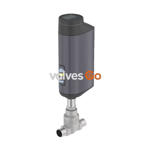
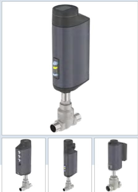
BURKERT 377810 (Type 3361) is an electromotive 2-way globe control valve engineered for precision fluid regulation in continuous process applications. Combining a brushless DC linear actuator with a precision ball screw drive, the unit positions the control cone with a positioning speed of 6 mm/s and a dead band of ±0.1%, ensuring rapid response without pressure-induced position deviation.
Specific article configuration 377810 integrates a DIN EN 1092-1 DN 25 flanged body in cast stainless steel CF3M, paired with a 20 mm (3/4") seat orifice and an equal percentage 50:1 control cone. Actuation is delivered by an AG2 size linear drive exerting 1300 N nominal thrust at 24 V DC. Wetted sealing relies on an all-metal stainless steel 1.4571 seat seal delivering Class IV shut-off tightness, backed by spring-compensated PTFE V-ring stem packings.
| Parameter | Technical Specification (Article 377810) |
|---|---|
| Product Type | Electromotive 2-way globe control valve |
| Valve Construction | Type 3361, flow-optimised globe design |
| Nominal Diameter | DN 25 (1") |
| Port Connection | Flange DIN EN 1092-1 (FTF 1 per DIN EN 558-1) |
| Pressure Ratings | PN 25 (DIN EN 1333), Class 150 (DIN EN 1759) |
| Operating Pressure Range | 0 to 25 bar(g) |
| Orifice / Seat Size | 20 mm (3/4") |
| Full Stroke Capacity (Kvs) | 7.2 m³/h (Cv 8.4 gpm) |
| Flow Characteristic | Equal percentage, theoretical rangeability 50:1 |
| Flow Direction | Below seat (against closing direction, 2 → 1) |
| Seat Seal Material | Stainless steel 1.4571 (metallic seal) |
| Seat Leakage Class | Class IV (DIN EN 60534-4) |
| Medium Temperature Range | -40 °C to +185 °C |
| Ambient Temperature Range | -25 °C to +65 °C |
| Actuator Variant | AG2 (actuator size 2, 1300 N nominal thrust) |
| Positioning Speed / Closing Time | 6 mm/s / typical 3.3 s (range 3.3 to 6.6 s) |
| Power Supply | 24 V DC ±10% (maximum ripple 10%) |
| Current Consumption | Max. 3 A at maximum load; standby 2 to 5 W |
| Power Failure Safety Setting | Blocked in static position (without energy storage) |
| Control Signals | 1 analogue input, 1 digital input, 1 analogue output, 2 digital outputs |
| User Interface | Blind cover with internal push buttons and 4 DIP switches |
| Ingress Protection | IP65 / IP67 (DIN EN 60529), NEMA 4X |
Actuator and valve body components feature an enclosed, smooth-surface construction designed for resistance to weather, mechanical vibration, and cleaning detergents in accordance with Ecolab testing procedure F&E/P3-E No. 40-1.
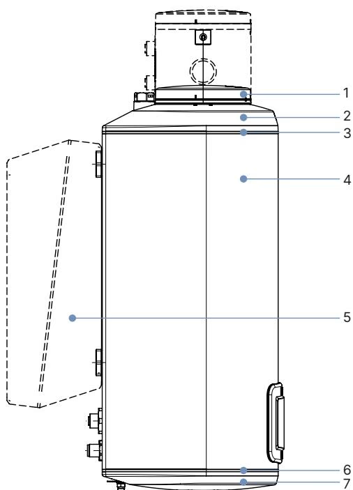
| Item | Component | Material |
|---|---|---|
| 1 | Blind cover / housing top | Polyphenylene sulphide (PPS) |
| 2 | Actuator cover | Polyphenylene sulphide (PPS) |
| 3 | Static seal | Ethylene propylene diene monomer (EPDM) |
| 4 | Actuator housing | Powder-coated aluminium |
| 6 | Housing seal | Ethylene propylene diene monomer (EPDM) |
| 7 | Actuator base | Polyphenylene sulphide (PPS) |
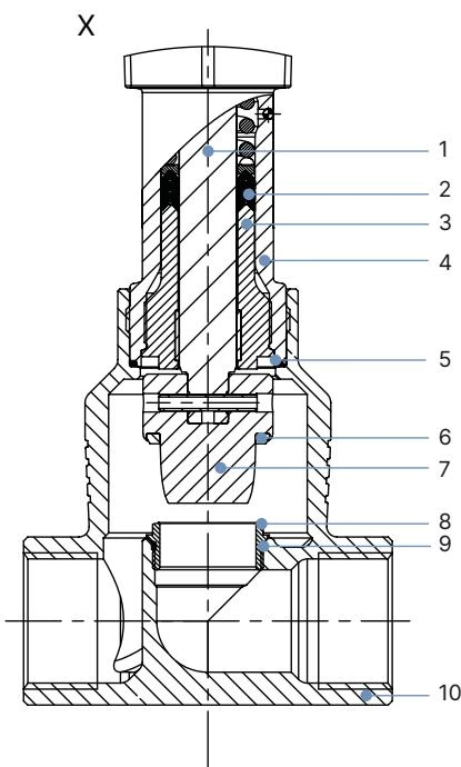
| Item | Component | Material |
|---|---|---|
| 1 | Valve spindle | Stainless steel 1.4401 (316) / 1.4404 (316L) |
| 2 | Spindle seal pack | Filled PTFE V-rings with spring compensation |
| 3 | Spindle guide | Stainless steel 1.4404 (316L) |
| 4 | Packing gland tube | Stainless steel 1.4401 (316) |
| 5 | Valve body seal | Graphite (or PTFE) |
| 6 | Seat seal | Stainless steel 1.4571 (metallic seat contact) |
| 7 | Control cone | Stainless steel 1.4571 |
| 8 | Valve seat | Stainless steel 1.4571 (threaded exchangeable design) |
| 9 | Seat O-ring | EPDM or PTFE |
| 10 | Valve body | Cast stainless steel CF3M |
Body geometry complies with DIN EN 1092-1 PN 25 face-to-face dimensions FTF 1 according to DIN EN 558-1.
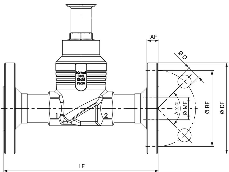
| Dimension Parameter | Symbol | Nominal Value (DN 25) |
|---|---|---|
| Face-to-face length | LF | 160 mm |
| Flange outer diameter | ∅ DF | 115 mm |
| Bolt circle diameter | ∅ BF | 85 mm |
| Flange thickness | AF | 18 mm |
| Bolt hole diameter | ∅ D | 14 mm |
| Bolt holes quantity & angle | A × α | 4 × 90° |
| Raised face / internal bore | ∅ MF | 29.7 mm |
| Actuator height (standard variant) | H1 | 446 mm |
| Closed position clearance allowance | — | Additional approx. 2 mm rise |
Flow passes beneath the valve seat (direction 2 → 1). The 20 mm seat orifice achieves a theoretical rangeability of 50:1 with equal percentage profiling according to DIN EN 60534-2-4.
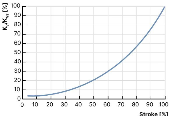
| Stroke Position | Kv Value [m³/h] |
|---|---|
| 5% | 0.20 |
| 10% | 0.25 |
| 20% | 0.31 |
| 30% | 0.47 |
| 40% | 0.70 |
| 50% | 1.10 |
| 60% | 1.60 |
| 70% | 2.50 |
| 80% | 3.80 |
| 90% | 5.40 |
| 100% (Kvs) | 7.20 |
Leakage Tightness
Metallic sealing on stainless steel 1.4571 provides Class IV shut-off tightness (permissible leakage ≤ 0.01% of nominal flow rate). Metallic seats maintain continuous operation across thermal cycling without seat deformation.
Article 377810 features analogue setpoint control and status feedback via an integrated terminal arrangement/circular connector layout and internal configuration switches.
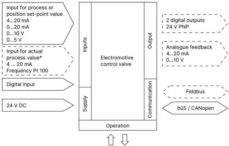
| Signal Function | Electrical Parameters |
|---|---|
| Analogue Setpoint Input | 0/4 to 20 mA (input resistance 70 Ω) or 0 to 5/10 V (resistance 22 kΩ); galvanically isolated |
| Analogue Actual Output | 0/4 to 20 mA (load 0 to 800 Ω) or 0 to 5/10 V (max. load current 10 mA) |
| Digital Control Input | 0 to 5 V = logical "0", 10 to 30 V = logical "1" (invertible) |
| Digital Outputs (2 channels) | Transistor output PNP, current limited to 100 mA |
| Operating Voltage | 24 V DC ±10%, max. 3 A peak current during movement |
| Service Communication | büS service interface accessed via USB-büS interface set for Bürkert Communicator software |
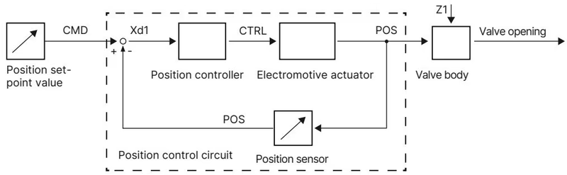
Control operations and local commissioning take place beneath the bayonet blind cover on the actuator top:
Mechanical Manual Override Restrictions
Mechanical manual actuation must only be conducted in a fully de-energised state. Insert a 3 mm Allen key into the manual override mechanism located beneath the blind cover. Rotate counter-clockwise to open and clockwise to close. Never exceed the maximum torque limit of 2 Nm.
The X.TUNE routine aligns internal position sensor measurements with physical mechanical stroke end stops. Calibration is necessary upon initial installation, actuator replacement, or valve seat servicing.
Pressure Hazard During Calibration
Never execute X.TUNE under line pressure. Running calibration while media pressure is applied causes severe controller misadjustment and uncalibrated stroke tracking.
| Fastener / Connection Location | Tool / Interface | Tightening Torque |
|---|---|---|
| Body connection (Actuator to DN 25 body) | Open-end wrench on body flats | 60 ± 3 Nm |
| Replaceable valve seat (Seat size 20 mm) | Installation tool (Ref. 652605) | 28 + 3 Nm |
| Spindle guide (14 mm spindle, DN 25) | Modified socket wrench SW21 | 25 Nm |
| Actuator base screws (AG2 housing) | Hexalobular / Allen key | 5 Nm |
| Actuator cover screws | Hexalobular internal key T25 | 5 Nm |
Explore similar products in our catalog


