

PN16

BURKERT 43084 is a Type 0256 direct-acting 2/2-way solenoid valve with G 1/4 brass body, 6 mm orifice, FKM seals, and 24V DC coil for neutral and hot media from 0 to 2 bar.
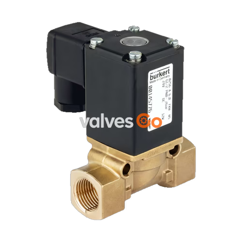
BURKERT 43084 is a complete Type 0256 direct-acting 2/2-way plunger solenoid valve engineered for shut-off, dosing, and control of neutral liquids and gases as well as technical vacuum. Featuring circuit function A (normally closed), the unit opens when energized and shuts tight when de-energized. The assembly is built with a forged brass body with G 1/4 internal thread ports, a 6.0 mm orifice, an epoxy-encapsulated class H coil rated for 24 V DC continuous duty (100% ED), and FKM seals designed for operating media temperatures from -10 °C to +130 °C at differential pressures from 0 to 2 bar.
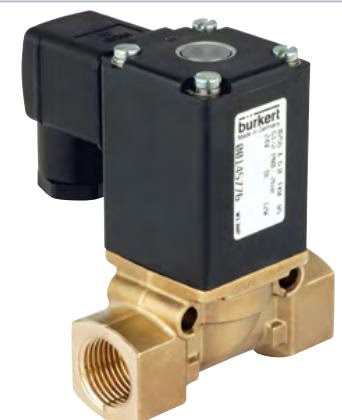
BURKERT 43084 operates as a direct-acting plunger valve without requiring any minimum differential pressure for actuation. Flow is routed above the valve seat, providing zero-bar operating capability and stable sealing under vacuum conditions.
| Parameter | Technical Value |
|---|---|
| Product Type | Type 0256 direct-acting plunger valve |
| Circuit Function | WW A (2/2-way, normally closed) |
| Article Number (MPN) | 043084 |
| Port Connection 1 & 2 | G 1/4 internal thread |
| Orifice Size (DN) | 6.0 mm (1/4") |
| Flow Capacity Kv (Water) | 0.8 m³/h |
| Flow Capacity QNn (Gas) | 860 l/min |
| Pressure Range (Liquids & Gases, DC) | 0.00 bar to 2.00 bar (gauge pressure) |
| Vacuum Capability | Technical vacuum |
| Operating Voltage | 24 V DC (voltage tolerance ±10%) |
| Duty Cycle | 100% ED continuous rating |
| Thermal Insulation Class | Class H (epoxy coil) |
| Switching Time Opening (DC) | 20 ms to 80 ms (measured at +20 °C, 6 bar inlet pressure) |
| Switching Time Closing (DC) | 20 ms to 30 ms (measured at +20 °C, 6 bar inlet pressure) |
| Medium Temperature Range (FKM) | -10 °C to +130 °C |
| Maximum Ambient Temperature | +55 °C |
| Maximum Medium Viscosity | 21 mm²/s (21 cSt) |
| Protection Class | IP65 (with cable plug attached) |
| Flow Direction | Directed above seat (indicated by arrow on body) |
In circuit function A, the 2/2-way valve remains closed when de-energized. The internal spring holds the plunger against the valve seat. Energizing the coil pulls the core upward, opening the orifice directly without hydraulic assistance.
INFO
Operating parameters are specified at an ambient temperature of up to +55 °C. For extended periods of downtime, actuating the valve 1 to 2 times per day maintains functional reliability.
Component materials are selected for chemical compatibility with oxygen, hot air, hot oils, and oils with additives.
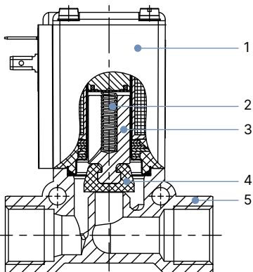
| Item No. | Component | Material |
|---|---|---|
| 1 | Coil | Epoxy |
| 2 | Spring | Stainless steel 1.4310 |
| 3 | Core / Plunger | Stainless steel 1.4105 |
| 4 | Seal | FKM (Fluor rubber) |
| 5 | Valve Body | Brass (Messing) |
BURKERT 43084 utilizes the 74.5 mm brass body execution with wrench flat width of 22 mm.
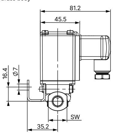
| Body Material | Port Thread D | Thread Depth F [mm] | Total Height H [mm] | Body Length L [mm] | Wrench Flat SW [mm] |
|---|---|---|---|---|---|
| Brass | G 1/4 | 12 | 91 | 74.5 | 22 |
| Brass | G 3/8 | 12 | 91 | 74.5 | 22 |
| Brass | G 1/2 | 14 | 94 | 74.5 | 27 |
For mounting onto machine surfaces or manifold plates, a dedicated mounting kit (article no. 151287) is available separately. It includes a clamp bracket and two M5 × 35 cheese-head screws. The distance between the M5 threaded bores is 37 mm, and the distance between the Ø 7 mm mounting holes is 48 mm.
The table below details the Burkert ordering chart for Type 0256 valves featuring the 74 mm brass housing, with article 043084 highlighted in its exact configuration.
| Port | Orifice [mm] | Kv (Water) [m³/h] | Pressure DC [bar] | Pressure AC Liq. [bar] | Pressure AC Gas [bar] | Seal | 24V DC | 24V 50Hz | 110V 50Hz | 230V 50Hz |
|---|---|---|---|---|---|---|---|---|---|---|
| G 1/4 | 4 | 0.5 | 0–6 | 0–12 | 0–16 | NBR | 055418 | 145729 | — | 054569 |
| G 1/4 | 6 | 0.8 | 0–2 | 0–4 | 0–8 | NBR | 145760 | 054924 | 054729 | 145763 |
| G 1/4 | 4 | 0.5 | 0–6 | 0–12 | 0–16 | FKM | 056010 | — | — | 145738 |
| G 1/4 | 6 | 0.8 | 0–2 | 0–4 | 0–8 | FKM | 043084 | — | 085459 | 054484 |
| G 3/8 | 6 | 0.8 | 0–2 | 0–4 | 0–8 | NBR | 055963 | 053680 | — | 054360 |
| G 3/8 | 10 | 1.5 | 0–0.4 | 0–1 | 0–1.5 | NBR | 145784 | 145805 | 040521 | 145786 |
| G 3/8 | 6 | 0.8 | 0–2 | 0–4 | 0–8 | FKM | — | — | — | 145804 |
| G 3/8 | 10 | 1.5 | 0–0.4 | 0–1 | 0–1.5 | FKM | 054672 | 058912 | — | 054673 |
| G 1/2 | 6 | 0.8 | 0–2 | 0–4 | 0–8 | NBR | 145771 | 057212 | 065499 | 145772 |
| G 1/2 | 8 | 0.9 | 0–0.5 | 0–1.5 | 0–2.5 | NBR | 040532 | 043220 | 065361 | 056421 |
| G 1/2 | 10 | 1.5 | 0–0.4 | 0–1 | 0–1.5 | NBR | 145788 | 145789 | 145790 | 120133 |
| G 1/2 | 12 | 1.8 | 0–0.1 | 0–0.5 | 0–1 | NBR | 145796 | 145797 | — | 145799 |
| G 1/2 | 6 | 0.8 | 0–2 | 0–4 | 0–8 | FKM | 145776 | 051894 | 054696 | 055163 |
| G 1/2 | 8 | 0.9 | 0–0.5 | 0–1.5 | 0–2.5 | FKM | 058779 | 064865 | — | 045502 |
| G 1/2 | 10 | 1.5 | 0–0.4 | 0–1 | 0–1.5 | FKM | 145806 | 145792 | — | 054983 |
| G 1/2 | 12 | 1.8 | 0–0.1 | 0–0.5 | 0–1 | FKM | 057676 | 241863 | — | 145801 |
The device uses contact pins configured to Form A acc. to DIN EN 175301-803. A standard mating cable plug is included in the package.
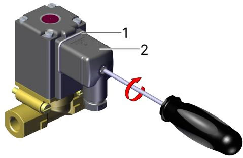
Electrical Safety
Connect the protective grounding conductor before applying voltage. Check electrical continuity between the coil body and the valve housing. Tighten the central cable plug screw with a maximum torque of 1 Nm.
Installation position is optional, but positioning the solenoid actuator upright is recommended to minimize particulate settling.
Piping Preparation
Clean and flush all pipelines thoroughly prior to valve installation. Install a pipeline strainer with mesh size ≤ 500 µm upstream of the valve inlet port.
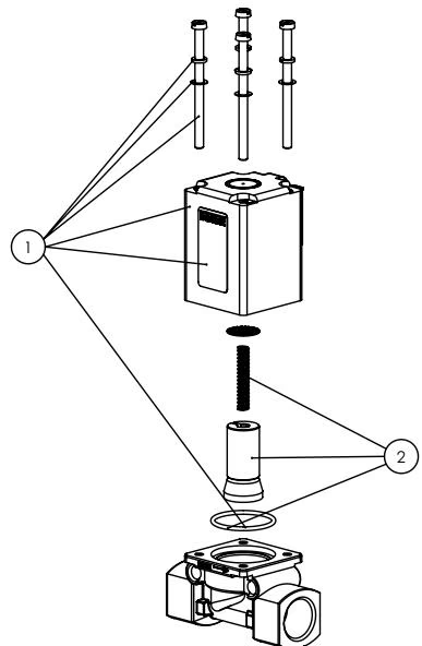
Under normal operating conditions, BURKERT 43084 operates maintenance-free. If internal contamination or seat wear occurs, original Bürkert replacement sets can be installed.
Explore similar products in our catalog


