

PN16

Burkert 465020 (Type 5420) is a pilot-controlled 4/2-way servo-diaphragm pneumatic solenoid valve with NPT 1/8 ports, 24 V DC coil, 2.5–10 bar operating pressure, and 150 l/min flow rate.
BURKERT 465020 (Type 5420) is a pilot-controlled 4/2-way seat valve equipped with servo-diaphragms for pneumatic systems. Configured in circuit function G (normally open), the valve routes inlet port 1 (P) to working port 2 (B) while exhausting working port 4 (A) through exhaust port 3 (R) when de-energized. The unit features internal NPT 1/8 threaded connections, an aluminium working port interface, a polyamide (PA) valve body, and an integrated manual override. A minimum differential pressure of 2.5 bar is required for switching across the operating pressure range of 2.5 to 10 bar.

Type 5420 operates as a poppet seat valve piloted via integrated servo-diaphragms. Switching actuation is electrical, paired with a hybrid return system combining a pneumatic spring and a mechanical spring. The push-over solenoid coil utilizes an AC10 coil system with a 32 mm width profile, isolated from fluid media. Exhaust air flow can be throttled directly on the valve or manifold.
| Parameter | Specification |
|---|---|
| Orifice size DN | 3.0 mm (main valve), 1.1 mm (pilot control) |
| Flow rate (QNn air) | 150 l/min (air at +20 °C, 6 bar inlet, 1 bar Δp) |
| Operating pressure | 2.5 to 10 bar |
| Minimum switching differential | 2.5 bar |
| Nominal voltage | 24 V DC (tolerance ±10%) |
| Electrical power consumption | 2 W |
| Operating medium | Neutral gases, lubricated or dry compressed air |
| Compressed air quality | ISO 8573-1:2010, Class 7.4.4 |
| Medium temperature | -10 °C to +60 °C |
| Ambient temperature | -10 °C to +55 °C |
| Response time opening | 30 ms (pressure build-up 0 to 90%) |
| Response time closing | 20 ms (pressure decay 100 to 10%) |
| Duty cycle | 100% continuous operation |
| Valve weight | Approx. 0.4 kg |
Compressed Air Dew Point
To prevent condensation and freezing of expanding compressed air, the pressure dew point must remain at least 10 K lower than the operating medium temperature.
Operating Pressure Limit
A differential pressure of at least 2.5 bar must be maintained across the valve. Operating below 2.5 bar differential will prevent full poppet switching.
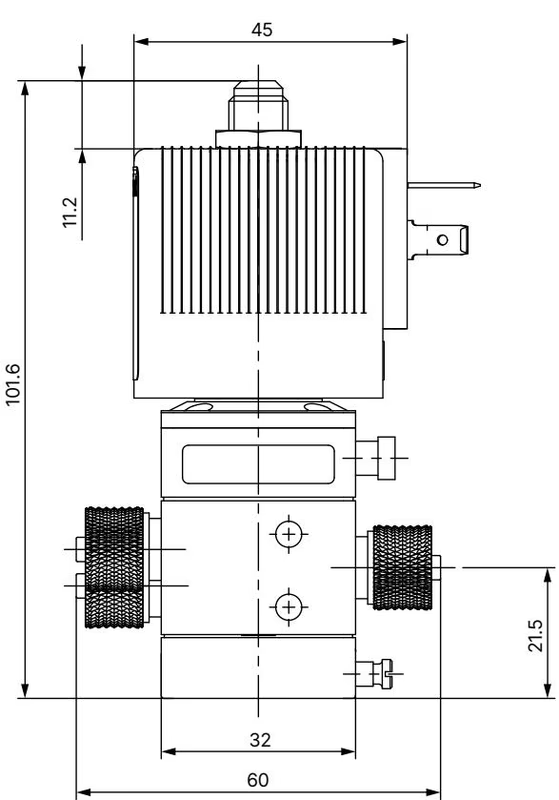
Type 5420 mounts either as a stand-alone inline valve or grouped onto two-channel pneumatic supply manifolds. Valve mounting is accomplished via four M4 x 8 mm tapped holes located on the underside of the body. Station width when banked is 33 mm per unit.
Mounting Orientation
Installation orientation is universal, but mounting with the solenoid coil upright is recommended to prevent particulate matter from settling into the core guide tube.
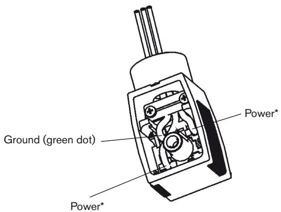
Electrical connection is established via plug contacts matching Form A per DIN EN 175301-803. The terminal interface accommodates Burkert cable plug Type 2518 or Type 2509. When correctly mated with the included seal, the connection delivers IP65 ingress protection.
| Article No. | Circuit Function | Port Connection (1 & 3) | Port Connection (2 & 4) | Voltage / Frequency | Power Consumption | QNn (Air) |
|---|---|---|---|---|---|---|
| 465020 | CF G | NPT 1/8 | NPT 1/8 | 24 V DC | 2 W | 150 l/min |
| 134622 | CF G | G 1/8 | G 1/8 | 24 V DC | 2 W | 200 l/min |
| 134623 | CF G | G 1/8 | G 1/8 | 24 V 50/60 Hz | 11 VA (inrush) / 6 VA | 200 l/min |
| 134625 | CF G | G 1/8 | G 1/8 | 230 V 50/60 Hz | 11 VA (inrush) / 6 VA | 200 l/min |
| 134630 | CF G | Hose 6/4 mm | Hose 6/4 mm | 24 V DC | 2 W | 200 l/min |
| 134634 | CF G | Manifold flange | G 1/8 | 24 V DC | 2 W | 200 l/min |
| 134638 | CF G | Manifold flange | Flange 6/4 mm | 24 V DC | 2 W | 200 l/min |
Stackable aluminium manifolds support centralized air supply for multiple Type 5420 stations:
| Manifold Type | Total Length A (mm) | Hole Spacing B (mm) | Article No. |
|---|---|---|---|
| 2-fold station | 75 | 87 | 005356 |
| 3-fold station | 108 | 120 | 005357 |
| 4-fold station | 141 | 153 | 005372 |
| 5-fold station | 174 | 186 | 005373 |
| 6-fold station | 207 | 219 | 005374 |
| 8-fold station | 273 | 285 | 006553 |
Cable plugs are ordered separately from the valve unit:
If the valve fails to switch during operation, verify the following mechanical and electrical checkpoints:
Explore similar products in our catalog


