

PN16

BURKERT 53969 (Type 0331) direct-acting 3/2-way NC solenoid valve features pivoted armature media separation, brass body, EPDM seal, DN 3 mm orifice, 0-10 bar operating pressure, and 24 V DC operation.
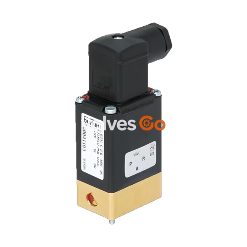
BURKERT 53969 (Type 0331) is a direct-acting, media-separated 3/2-way pivoted armature solenoid valve configured in circuit function C (normally closed). It features a brass valve body, EPDM seals, and a 3.0 mm nominal orifice. Designed for sub-base installation via the Bürkert-specific flange interface (32 mm x 46 mm, version A2), this complete valve unit operates on 24 V DC with a rated operating pressure range from 0.00 bar to 10.00 bar. The water flow coefficient Kv reaches 0.12 m³/h, and the standard gas flow rate QNn is 130 l/min.
The pivoted armature mechanism isolates the magnetic actuator from the fluid path using a flexible diaphragm barrier. This physical separation prevents medium contact with metallic coil components, making Type 0331 suitable for aggressive or sensitive media within a fluid temperature span of -30 °C to +90 °C. The valve assembly includes an integrated manual override for commissioning and function tests, an epoxy-encapsulated Class H coil, and an enclosed DIN EN 175301-803 Form A cable plug achieving IP65 enclosure protection.
Type 0331 uses a pivoted armature drive where the magnetic core tilts rather than slides within the media chamber. Because the armature does not slide inside the fluid, the construction eliminates sliding seal friction, particle entrapment, and premature mechanical wear. The separating diaphragm isolates the solenoid actuator from the fluid cavity, ensuring clean fluid handling and chemical resistance.
The integrated manual override is positioned on the valve top, allowing manual switching during commissioning, emergency override, or system maintenance without applying electrical power. To prevent accidental manual triggering in critical processes, an optional circlip accessory can be fitted to mechanically lock the manual lever.
Article 53969 operates under Circuit Function C: a direct-acting 3/2-way valve that is normally closed in its de-energized state. In this unpowered state, pressure supply port 1 (P/NC) is shut off, while service outlet port 2 (A/OUT) vents directly through exhaust port 3 (R/NO). Upon energizing the 24 V DC coil, the pivoted armature shifts: inlet port 1 connects to outlet port 2, and exhaust port 3 is closed.
| Circuit Function | Valve Type Description | Port 1 | Port 2 | Port 3 |
|---|---|---|---|---|
| WW A | 2/2-way direct-acting, normally closed | P | A | — |
| WW B | 2/2-way direct-acting, normally open | — | B | P |
| WW C (53969) | 3/2-way direct-acting, normally closed | P | A | R |
| WW D | 3/2-way direct-acting, normally open | R | B | P |
| WW E | 3/2-way mixing valve | P1 | A | P2 |
| WW F | 3/2-way distribution valve | A | P | B |
| WW T | 3/2-way direct-acting, universal flow direction | NC | IN/OUT | NO |
Port Mapping for Article 53969
On the standard Bürkert sub-base flange interface, Port 1 corresponds to fluid supply (P), Port 2 serves as working output (A), and Port 3 acts as the exhaust or return channel (R).
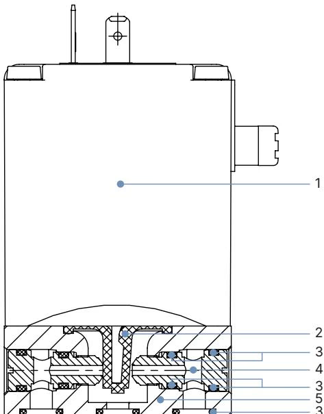
The physical construction of Type 0331 utilizes high-grade engineering polymers and metallurgies matched to demanding fluid conditions:
| Item | Component | Material (Article 53969) | Family Material Options |
|---|---|---|---|
| 1 | Solenoid coil | Epoxy encapsulation | Epoxy (Class H insulation) |
| 2 | Diaphragm | EPDM (70 Shore A) | EPDM, FKM, FFKM, NBR |
| 3 | O-ring seals | EPDM | EPDM, FKM, FFKM, NBR |
| 4 | Valve seat | Brass | Brass, Stainless steel (1.4401), PP, PEEK |
| 5 | Valve body | Brass | Brass, Stainless steel (1.4401), PP, PEEK, PVDF |
EPDM sealing material is chemically resistant to alkalis, low-to-medium concentration acids, alkaline washing solutions, and bleaching lyes. For mineral oils or fuel applications, NBR or FKM configurations must be selected instead.
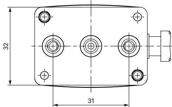
BURKERT 53969 is built on the standard Bürkert sub-base flange interface (SFB version A2), enabling direct mounting onto multi-station manifolds or custom control blocks. Key structural dimensions:
In standard DC operation, Type 0331 coils consume 11 W cold and 8 W warm, delivering 100% ED continuous duty rating on brass and stainless steel bodies.
| Characteristic | Specification (53969) | Family Range (Type 0331) |
|---|---|---|
| Nominal orifice (DN) | 3.0 mm (1/8") | DN 2.0 mm to DN 4.0 mm |
| Flow factor Kv (Water) | 0.12 m³/h | 0.08 m³/h (DN 2 DC) to 0.18 m³/h (DN 4 AC) |
| Standard flow rate QNn (Gas) | 130 l/min | — |
| Operating pressure range | 0.00 – 10.00 bar | 0 – 16 bar (DN 2), 0 – 10 bar (DN 3), 0 – 5 bar (DN 4) |
| Vacuum capability | Down to -0.98 bar | -0.98 bar to rated limits across all seal types |
| Switching time: opening | 10–20 ms | 8–15 ms (AC), 10–20 ms (DC) |
| Switching time: closing | 10–20 ms | 8–15 ms (AC), 10–20 ms (DC) |
| Voltage rating | 24 V DC (±10% tolerance) | 12 V DC, 24 V DC, 24 V/50 Hz, 110 V/50 Hz, 230 V/50 Hz |
| Power consumption (DC) | Cold: 11 W, Warm: 8 W | Standard DC: 11 W / 8 W; AC: 30 VA inrush, 15 VA / 8 W hold |
| Medium viscosity | Max. 37 mm²/s | Max. 37 mm²/s |
Switching times are measured according to DIN standards at +20 °C and 6 bar pressure at the valve outlet. Opening corresponds to a pressure build-up from 0% to 90%, while closing corresponds to a pressure reduction from 100% down to 10%.
The internal compression springs in Type 0331 valves are calibrated specifically for each circuit function. When a valve built for one function is connected in a different configuration, the maximum allowable operating pressure adjusts according to internal spring bias:
| Original Function | DN | Permissible Working Pressure in New Function [bar] (Metal Body, 8 W / 11 W) | |||||
|---|---|---|---|---|---|---|---|
| A | B | C | D | E | F | ||
| C (53969 base) | DN 2 | 16 bar | 1.5 bar | 16 bar | 1.5 bar | 1.5 bar | 16 bar |
| C (53969 base) | DN 3 | 10 bar | 1.0 bar | 10 bar | 1.0 bar | 1.0 bar | 10 bar |
| C (53969 base) | DN 4 | 5 bar | 0.8 bar | 5 bar | 0.8 bar | 0.8 bar | 5 bar |
| D | DN 3 | 2.5 bar | 10 bar | 2.5 bar | 10 bar | 2.0 bar | 3.0 bar |
| T | DN 3 | 6.0 bar | 6.0 bar | 6.0 bar | 6.0 bar | 6.0 bar | 6.0 bar |
BURKERT 53969 is supplied with standard terminal tags matching DIN EN 175301-803 Form A. An enclosed cable plug provides IP65 protection when secured with its central tightening screw.
Safety Instructions for Servicing
Before conducting maintenance or dismounting the valve, depressurize and fully drain fluid lines. Disconnect power supplies and ensure systems cannot be re-energized accidentally. Protective earth conductors must remain continuously connected.
Type 0331 modular sub-base valves integrate with factory manifold assemblies and auxiliary electronics:
Explore similar products in our catalog


