PN16
Spirax Sarco FT43 cast iron bodied ball float steam trap with stainless steel internals and automatic air venting facility. Available in sizes DN25 to DN50, with PN16 flanged connections. Ideal for horizontal or vertical flow, handling up to 13 bar g operating pressure.
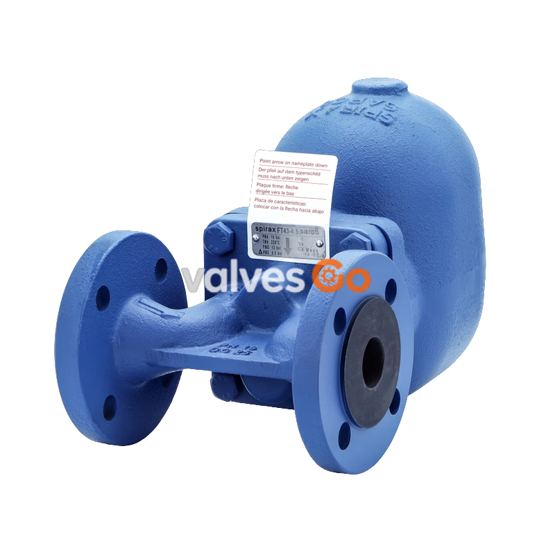
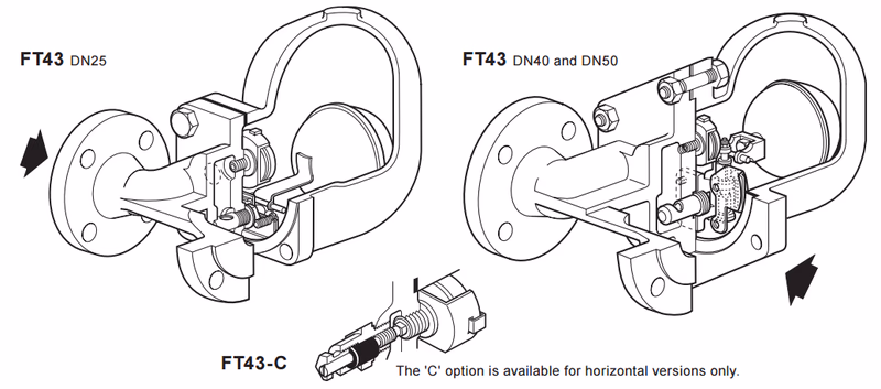
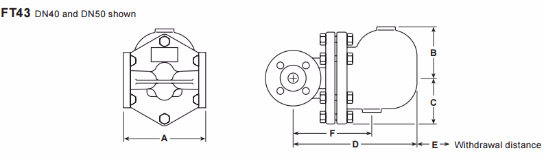
The FT43 is a cast iron bodied ball float steam trap having stainless steel working internals and automatic air venting facility. The trap is supplied with integrally flanged connections and can be maintained without disturbing the pipework. Vertical flanged connections are available for all sizes. Flow direction for the horizontal trap is clearly illustrated on the body. For vertically orientated traps, the flow is downwards only.
Product Features
| Size | Flange Standard | Notes |
|---|---|---|
| DN25 | EN 1092 PN16, ASME 125, JIS/KS 10 | Flow (FT43 horizontal): Left to Right (R-L versions available for PN16). Flow (FT43V vertical): Downwards. |
| DN40, DN50 | EN 1092 PN16, ASME 125 | Flow (FT43 horizontal): Right to Left. Flow (FT43V vertical): Downwards. |
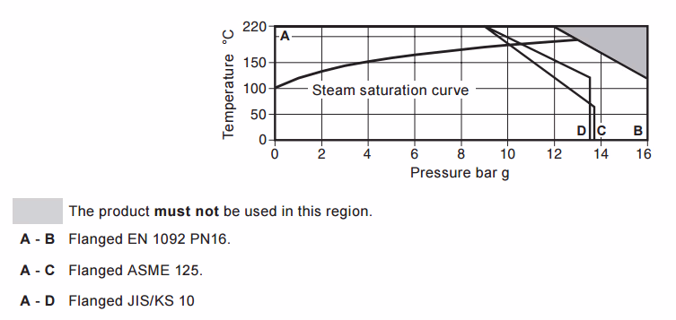
Standard flanges are EN 1092 PN16 with face-to-face dimensions in accordance with EN 26554 (Series 1).Note: ASME flanges are supplied with tapped holes to receive flange bolts. JIS/KS flanges will be supplied drilled as normal with plain bolt holes.
| Parameter | Value |
|---|---|
| Body Design Conditions | PN16 |
| Maximum Allowable Pressure (PMA) | 16 bar g @ 120 °C |
| Maximum Allowable Temperature (TMA) | 220 °C @ 12.1 bar g |
| Minimum Allowable Temperature | 0 °C |
| Maximum Operating Pressure (PMO) | 13 bar g @ 195 °C (for saturated steam service) Note: The DN40 and DN50 traps are limited to a PMO equal to PMX |
| Maximum Operating Temperature (TMO) | 220 °C @ 12.1 bar g |
| Minimum Operating Temperature | 0 °C |
| Maximum Differential Pressure (ΔPMX) | FT43-4.5: 4.5 bar FT43-10: 10 bar FT43-14: 13 bar |
| Maximum Cold Hydraulic Test Pressure | 24 bar g Note: With internals fitted, test pressure must not exceed ΔPMX |
| No. | Part | Material | Standard |
|---|---|---|---|
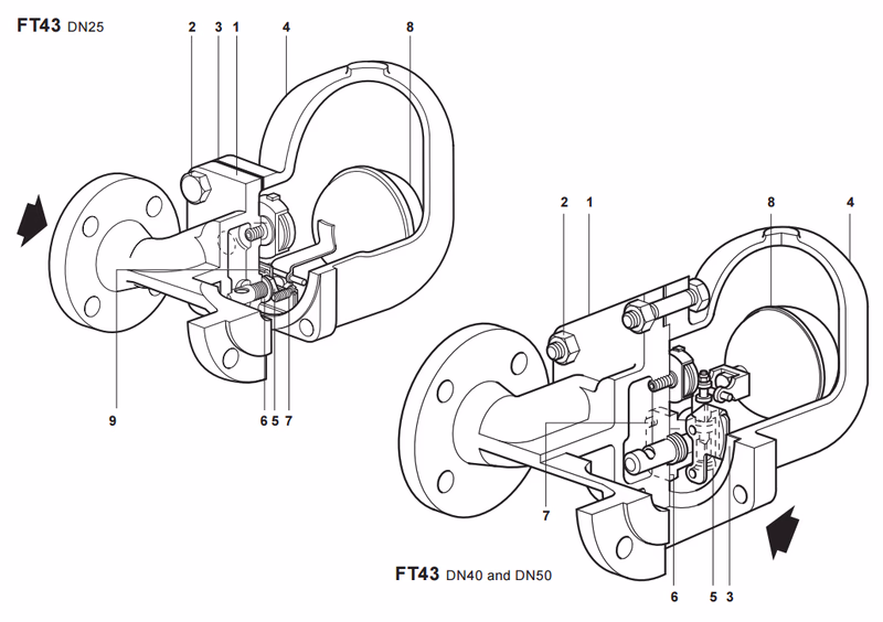
| 1 | Body | Cast iron | EN-JL 1040 |
| 2 | Cover bolts (DN25) | Steel | BS 3692 Gr. 8.8 |
| 2 | Cover stud | Steel | BS 4882 - B7M |
| 2 | Cover nuts | Steel | BS 3692 Gr. 8.8 |
| 3 | Cover gasket | Reinforced exfoliated graphite | - |
| 4 | Cover | Cast iron | EN-JL 1040 |
| 5 | Valve seat (DN25) | Stainless steel | BS 970 431 S29 |
| 5 | Main valve assembly with erosion deflector (DN40, DN50) | Stainless steel | BS 3146 Part 2 Anc 2 |
| 6 | Valve seat gasket (DN25) | Stainless steel | BS 1449 304 S11 |
| 6 | Main valve assembly gasket (DN40, DN50) | Reinforced exfoliated graphite | - |
| 7 | Pivot frame assembly bolts (DN25) | Stainless steel | BS 4183 18/8 |
| 7 | Main valve assembly bolts (DN40) | - | BS 970 304 S16 |
| 7 | Studs and nuts (DN50) | - | BS 6105 A4.80 |
| 8 | Ball float and lever (DN25) | Stainless steel | BS 1449 304 S16 |
| 8 | Ball float (DN40, DN50) | Stainless steel | BS 1449 304 S16 |
| 9 | Support frame | Stainless steel | BS 1449 304 S16 |
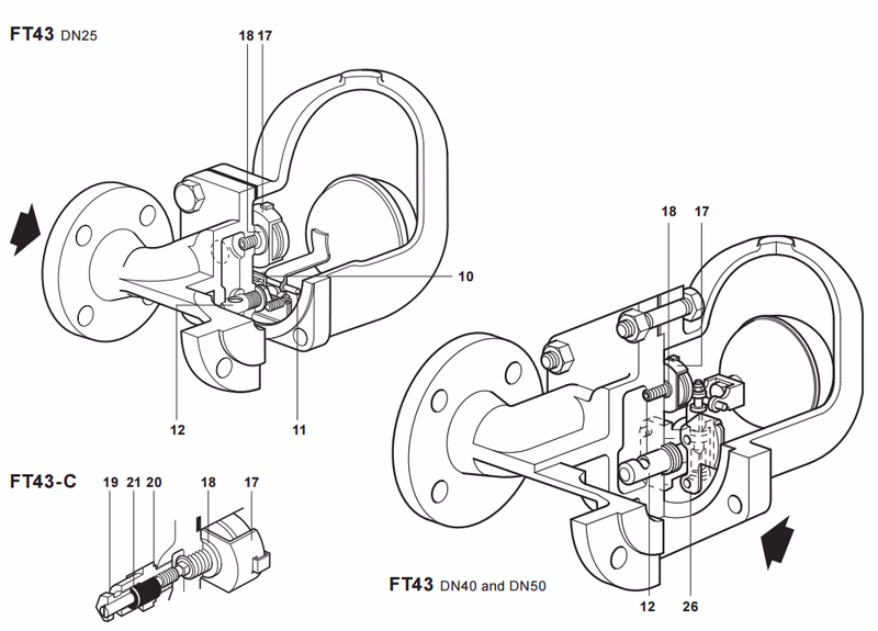
| 10 | Pivot frame | Stainless steel | BS 1449 304 S16 |
| 11 | Pivot pin | Stainless steel | - |
| 12 | Erosion deflector | Stainless steel | BS 970 431 S29 |
| 17 | Air vent assembly | Stainless steel | - |
| 18 | Air vent seat gasket | Stainless steel | BS 1449 409 S19 |
| 19 | SLR assembly | Stainless steel | BS 970 303 S21 |
| 20 | SLR gasket | Mild steel | BS 1449 CS4 |
| 21 | SLR seal | Graphite | - |
| 26 | Inlet plate (DN40, DN50) | Stainless steel | BS 1449 304 S15 |
| Size | A (mm) | B (mm) | C (mm) | D (mm) | E (mm) | F (mm) | Weight (kg) |
|---|---|---|---|---|---|---|---|
| DN25 | 160 (PN16) / 148 (ASME 125) | 110 | 80 | 245 | 160 | 215 | 8.3 |
| DN40 | 230 (PN16) / 221 (ASME 125) | 128 | 110 | 330 | 200 | 200 | 21.5 |
| DN50 | 230 (PN16) / 220 (ASME 125) | 140 | 126 | 340 | 200 | 225 | 30.5 |
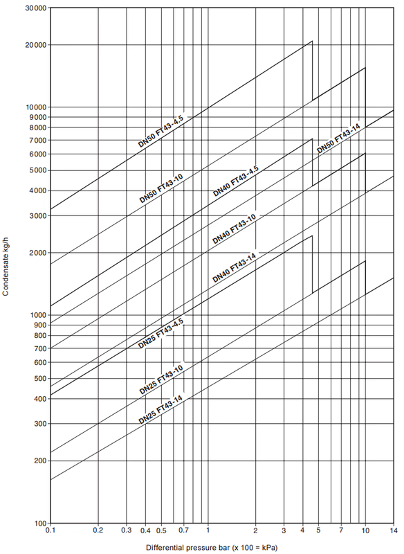
Capacities shown are based on condensate at saturation temperature. Under start-up conditions when the condensate is cold the internal thermostatic air vent will be open and provides additional capacity to the main valve.
| ΔP (bar) | 0.5 | 1 | 2 | 3 | 4.5 | 7 | 10 | 14 |
|---|---|---|---|---|---|---|---|---|
| DN25, DN40, DN50 | 460 | 680 | 900 | 1 080 | 1 300 | 1 600 | 1 980 | 2 050 |
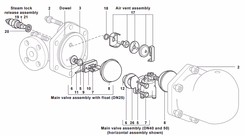
The spare parts available are shown in solid outline. Parts drawn in grey line are not supplied as spares.
Available spares:
* On horizontal traps the erosion deflector on the DN25 is pressed into the body during manufacture and not available as a spare.** There is no erosion deflector on vertical traps.
How to order spares: Always order spares by using the description given in the column headed 'Available spares' and state the size and type of trap, including pressure range and orientation i.e. horizontal or vertical connections. Example: 1 - Air vent assembly for a Spirax Sarco DN25 FT43-4.5 ball float steam trap, with horizontal connections.
| Item | Part / Size | Across Flats (A/F) | Thread Size / Bolt | Torque (N m) |
|---|---|---|---|---|
| 2 | DN25 | 17 A/F | M10 x 30 | 29 - 33 |
| DN40 | 19 A/F | M12 x 60 | 60 - 66 | |
| DN50 | 24 A/F | M16 x 70 | 80 - 88 | |
| 5 | DN25 | 50 - 50 | ||
| 7 | DN25 | M5 x 20 | 2.5 - 2.8 | |
| DN40 | 10 A/F | M6 x 20 | 10 - 12 | |
| DN50 | 13 A/F | M8 x 20 | 20 - 24 | |
| 17 | 17 A/F | 50 - 55 | ||
| 19 | 22 A/F | 50 - 55 |
For full details see the Installation and Maintenance Instructions (IM-S02-30) supplied with the product. Installation note: The FT43 must be installed with the direction of flow as indicated on the body, and with the float arm in a horizontal plane so that it rises and falls vertically.
This product is recyclable. No ecological hazard is anticipated with the disposal of this product providing due care is taken.
Example: 1 off Spirax Sarco DN25 FT43-4.5 ball float steam trap, flanged to EN 1092 PN16 with cast iron body and cover with thermostatic air vent.