PN16
Spirax Sarco FT44 carbon steel bodied ball float steam trap with stainless steel internals and automatic air venting. Available in DN15 to DN50, PN40, ASME 150/300 flanged connections. Ideal for high pressure applications up to 32 bar g.
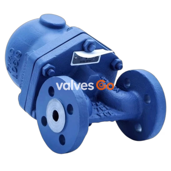
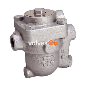
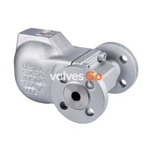
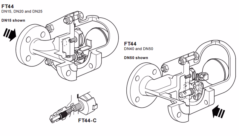
The FT44 is a carbon steel bodied ball float steam trap having stainless steel working internals and automatic air venting facility. The body and cover castings are produced by a TÜV approved foundry. The trap is supplied with integrally flanged connections and can be maintained without disturbing the pipework. Vertical flanged connections, designated FT44V, are available for all sizes. Flow direction for the horizontal trap is clearly illustrated on the body. For vertically orientated traps the flow is downwards only.
Product Features
DN15, DN20, DN25, DN40 and DN50.
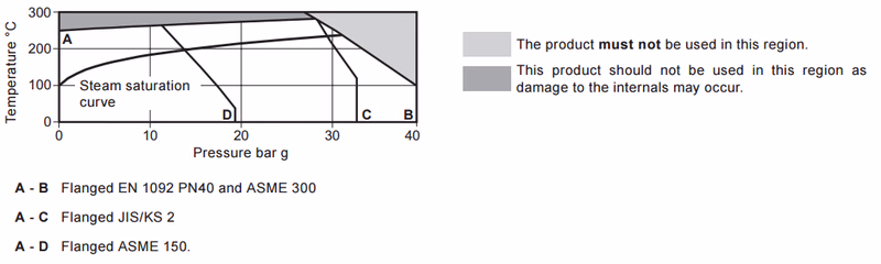
Note: ASME / JIS/KS flanges are supplied with tapped holes to receive flange bolts. ASME flanges have UNC threads and JIS/KS have metric threads.
| Parameter | Value |
|---|---|
| Body Design Conditions | PN40 |
| Maximum Allowable Pressure (PMA) | 40 bar g @ 100 °C |
| Maximum Allowable Temperature (TMA) | 300 °C @ 27.5 bar g |
| Minimum Allowable Temperature | -10 °C |
| Maximum Operating Pressure (PMO) | 32 bar g @ 239 °C (for saturated steam service) Note: The DN40 and DN50 traps are limited to a PMO equal to ΔPMX |
| Maximum Operating Temperature (TMO) | 285 °C @ 28.5 bar g |
| Minimum Operating Temperature | 0 °C |
Maximum Differential Pressure (ΔPMX):
| Size | DN15, DN20, DN25 | DN40, DN50 |
|---|---|---|
| FT44-4.5 | 4.5 bar | 4.5 bar |
| FT44-10 | 10 bar | 10 bar |
| FT44-14 | 14 bar | - |
| FT44-21 | 21 bar | 21 bar |
| FT44-32 | 32 bar | 32 bar |
Product is safe for use under full vacuum conditions.Designed for a maximum cold hydraulic test pressure: 60 bar g.Caution: The trap in its complete operational form must not be subjected to a pressure greater than 48 bar otherwise damage to the internal mechanism may result.
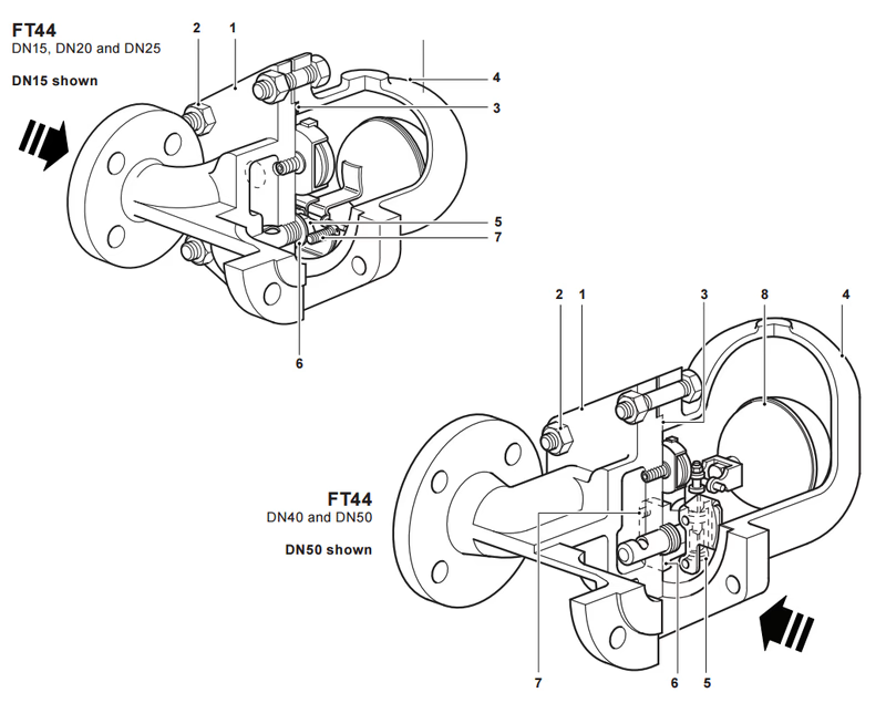
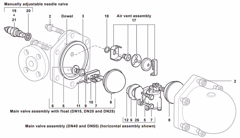
| No. | Part | Size / Note | Material | Standard |
|---|---|---|---|---|
| 1 | Body | Carbon steel | 1.0619+N/WCB | |
| 2 | Cover studs | Steel | BS 4882 B7M | |
| 2 | Cover nuts | DN15, DN20, DN25 | Steel | EN 10269 25 Cr Mo 4 |
| DN40, DN50 | Steel | BS 3692 Gr. 8 | ||
| 3 | Cover gasket | Reinforced exfoliated graphite | - | |
| 4 | Cover | Carbon steel | 1.0619+N/WCB | |
| 5 | Valve seat | DN15, DN20, DN25 | Stainless steel | BS 970 431 S29 |
| 5 | Main valve assembly with erosion deflector | DN40, DN50 | Stainless steel | BS 3146 Pt2 ANC2 / BS 970 416 S37 |
| 6 | Valve seat gasket | DN15, DN20, DN25 | Stainless steel | BS 1449 304 S11 |
| 6 | Main valve assembly gasket | DN40, DN50 | Reinforced exfoliated graphite | - |
| 7 | Pivot frame assembly screws | DN15, DN20, DN25 | Stainless steel | BS 4183 18/8 |
| 7 | Main valve assembly bolts | DN40 | Stainless steel | BS 970 302 S25 |
| 7 | Main valve assembly studs and nuts | DN50 | Stainless steel | BS 970 431 S29 |
| 8 | Ball float and lever | Stainless steel | BS 1449 304 S16 | |
| 9 | Support frame | DN15, DN20, DN25 | Stainless steel | BS 1449 304 S16 |
| 10 | Pivot frame | DN15, DN20, DN25 | Stainless steel | BS 1449 304 S16 |
| 11 | Pivot pin | DN15, DN20, DN25 | Stainless steel | - |
| 12 | Erosion deflector | Stainless steel | BS 970 431 S29 | |
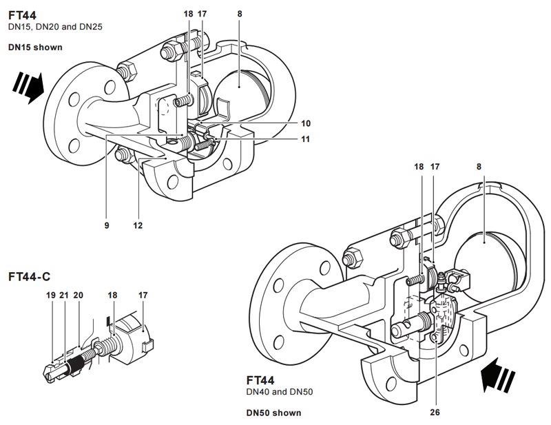
| 17 | Air vent assembly | Stainless steel | - | |
| 18 | Air vent seat gasket | Stainless steel | BS 1449 409 S19 | |
| 19 | SLR assembly | Stainless steel | BS 970 303 S31 | |
| 20 | SLR gasket | Steel | BS 1449 CS4 | |
| 21 | SLR seal | Graphite | - | |
| 26 | Inlet plate | DN40, DN50 only | Stainless steel | BS 1449 304 S16 |
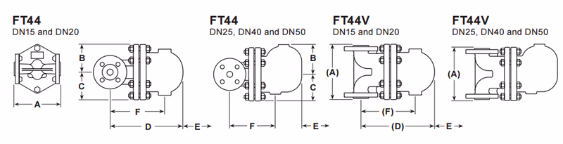
| Size | PN40 A (A) | ASME 300 A (A) | ASME 150 A (A) | JIS/KS 20K A (A) | B | C | D | (D) | E | F | (F) | Weight |
|---|---|---|---|---|---|---|---|---|---|---|---|---|
| DN15 | 150 (150) | 209 (150) | 203 (150) | 206 (150) | 80 | 80 | 215 | (215) | 120 | 155 | (155) | 10.8 |
| DN20 | 150 (150) | 209 (150) | 205 (150) | 210 (150) | 80 | 80 | 225 | (225) | 120 | 165 | (165) | 10.8 |
| DN25 | 160 (160) | 212 (160) | 208 (160) | 210 (160) | 115 | 85 | 276 | (280) | 170 | 215 | (218) | 15.0 |
| DN40 | 230 (230) | 327 (230) | 321 (230) | 322 (230) | 130 | 115 | 326 | (337) | 200 | 200 | (210) | 33.0 |
| DN50 | 230 (230) | 320 (230) | 313 (230) | 311 (230) | 141 | 123 | 332 | (347) | 200 | 235 | (250) | 34.0 |
(Dimensions in brackets relate to vertical connections only. PN40 face-to-face dimensions are in accordance with EN 26554 Series 1).
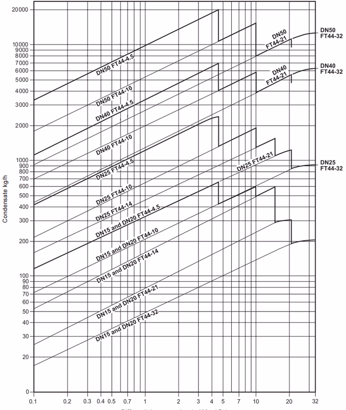
Capacities shown are based on condensate at saturation temperature. Under start-up conditions when the condensate is cold the internal thermostatic air vent will be open and provides additional capacity to the main valve.
Minimum additional cold water capacity (kg/h):
| ΔP (bar) | 0.5 | 1 | 2 | 3 | 4.5 | 7 | 10 | 14 | 21 | 32 |
|---|---|---|---|---|---|---|---|---|---|---|
| DN15 / DN20 (up to 21 bar) | 450 | 600 | 780 | 1040 | 1140 | 1350 | 1530 | 1750 | 2300 | - |
| DN15 / DN20 (32 bar only) | 170 | 250 | 380 | 520 | 600 | 780 | 860 | 1140 | 1170 | 1200 |
| DN25, DN40, DN50 (up to 21 bar) | 460 | 680 | 900 | 1080 | 1300 | 1600 | 1980 | 2050 | 2600 | - |
| DN25, DN40, DN50 (32 bar only) | 90 | 120 | 350 | 460 | 600 | 850 | 900 | 1020 | 1200 | 1300 |
The spare parts available are shown in solid outline. Parts drawn in a grey line are not supplied as spares.
Available spares:
* On horizontal traps the erosion deflector on the DN15, DN20 and DN25 is pressed into the body during manufacture and not available as a spare.** There is no erosion deflector on vertical traps.
| Item | Size | Across Flats (A/F) | Thread Size / Bolt | Torque (N m) |
|---|---|---|---|---|
| 2 | DN15, DN20, DN25 | 17 A/F | M10 x 60 | 19 - 22 |
| DN40 | 24 A/F | M16 x 85 | 60 - 66 | |
| DN50 | 24 A/F | M16 x 85 | 80 - 88 | |
| 5 | DN15, DN20, DN25 | 17 A/F | 50 - 55 | |
| 7 | DN15, DN20, DN25 | M5 x 20 | 2.5 - 2.8 | |
| DN40 | 10 A/F | M6 x 20 | 10 - 12 | |
| DN50 | 13 A/F | M8 x 20 | 20 - 24 | |
| 17 | 17 A/F | 50 - 55 | ||
| 19 | 22 A/F | 50 - 55 |
For full details see the Installation and Maintenance Instructions (IM-S02-30) supplied with the product. Installation note: The FT44 must be installed with the direction of flow as indicated on the body, and with the float arm in a horizontal plane so that it rises and falls vertically.
This product is recyclable. No ecological hazard is anticipated with the disposal of this product, providing due care is taken.
Example: 1 off Spirax Sarco DN25 FT44-14 ball float steam trap, flanged to EN 1092 PN40 with carbon steel body and cover and thermostatic air vent.