PN16
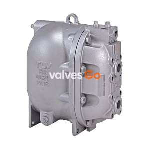
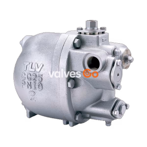
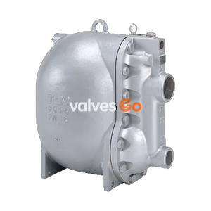
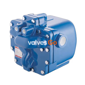
Spirax Sarco MFP14 automatic pumps are displacement receivers operated by steam or compressed air for lifting condensate and other liquids. The range includes SG iron, cast steel, and stainless steel body options, supports screwed and flanged connections, and provides full material, pressure, dimension, and sizing data for condensate recovery applications.
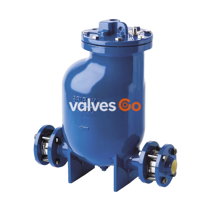
The Spirax Sarco MFP14 automatic pump is a displacement receiver operated by steam or compressed air. It is generally used to lift liquids such as condensate to a higher level. Subject to suitable operating conditions, the pump can also directly drain closed vessels under vacuum or pressure. When used with a float steam trap, it can effectively drain temperature-controlled heat exchangers under all operating conditions.
Available body materials:
| Body Material | Variant |
|---|---|
| SG iron | MFP14 |
| Cast steel | MFP14S |
| Stainless steel | MFP14SS |
This product complies with the European Pressure Equipment Directive 2014/68/EU and ATEX Directive 2014/34/EU, and is available with EN 10204 3.1 certification when specified.
1", 1 1/2", 2", and 3" x 2" screwed BSP T Rp (ISO 7-1)DN25, DN40, DN50, and DN80 x DN50 flanged EN 1092 PN16, ANSI B16.5 Class 150, and JIS/KS B2238 10DN50 flanged EN 1092 PN16, ANSI B16.5 Class 150, and JIS/KS B2238 102" screwed BSP T Rp (ISO 7-1) / NPT connections are available to special orderDN50 flanged EN 1092 PN16, ANSI B16.5 Class 150, and JIS/KS B2238 102" screwed BSP T Rp (ISO 7-1) / NPT connections are available to special orderA plugged boss is provided on the pump cover, screwed 1/2" BSP T Rp (ISO 7-1), for connecting an electronic pump monitor. For full details see TI-P136-24.
EPM1: Stand-alone unit with 8-digit LCD display powered by an integral 1.5 V lithium batteryEPM2: Version suitable for coupling to a remote counter or building energy management system (BEMS)An insulation jacket tailor-made for each size of MFP14 is available for energy saving and health and safety improvement. See TI-P136-07.
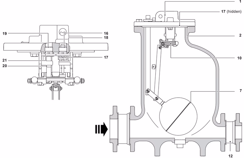
| No. | Part | Variant / Detail | Material / Grade |
|---|---|---|---|
| 1 | Cover | MFP14 | SG iron, (EN JS 1025) EN-GJS-400-18-LT |
| 1 | Cover | MFP14S | Cast steel, DIN GSC 25N / ASTM A216 WCB |
| 1 | Cover | MFP14SS | Stainless steel, BS EN 10213-4 144091 / ASTM A351 CF3M |
| 2 | Cover gasket | Synthetic fibre | |
| 3 | Cover screws | Stainless steel, ISO 3506 Gr. A2-70 | |
| 4 | Body | MFP14 | SG iron, (EN JS 1025) EN-GJS-400-18-LT |
| 4 | Body | MFP14S | Cast steel, DIN GSC 25N / ASTM A216 WCB |
| 4 | Body | MFP14SS | Stainless steel, BS EN 10213-4 144091 / ASTM A351 CF3M |
| 5 | Pillar | Stainless steel, BS 970 431 S29 | |
| 6 | Connector rod | Stainless steel, BS 1449 304 S11 | |
| 7 | Float and lever | Stainless steel, AISI 304 | |
| 8 | Eyebolt (integral) | MFP14 | SG iron, (EN JS 1025) EN-GJS-400-18-LT |
| 8 | Eyebolt (integral) | MFP14S | Cast steel, DIN GSC 25N / ASTM A216 WCB |
| 8 | Eyebolt (integral) | MFP14SS | Stainless steel, BS EN 10213-4 144091 |
| 9 | Mechanism lever | ASTM A351 CF3M / BS 3146 Pt.2 ANC 2 | |
| 10 | Spring | DN50 and DN80 | Inconel 718, ASTM 5962 / ASTM B367 |
| 11 | Pressure plug | DN40 | Stainless steel |
| 11 | Pressure plug | Other sizes | Steel, DIN 267 Part 1 Class 5.8 |
| 12 | Check valves | Stainless steel | |
| 13 | Screwed boss flanges | Steel | |
| 14 | Mechanism bracket | Stainless steel, BS 3146 Pt.2 ANC 4B | |
| 15 | Bracket screws | Stainless steel, BS 6105 Gr. A2-70 | |
| 16 | Inlet valve seat | Stainless steel, BS 970 431 S29 | |
| 17 | Inlet valve stem | Stainless steel, ASTM A276 440B | |
| 18 | Inlet valve seat gasket | Stainless steel, BS 1449 409 S19 | |
| 19 | Exhaust valve seat | Stainless steel, BS 970 431 S29 | |
| 20 | Exhaust valve | Stainless steel, BS 3146 Pt.2 ANC 2 | |
| 21 | Exhaust valve seat gasket | Stainless steel, BS 1449 409 S19 | |
| 22 | EPM actuator | ALNICO | |
| 23 | O-ring seal | EPDM | |
| 28 | Spring anchor | Stainless steel, BS 970 431 S29 |
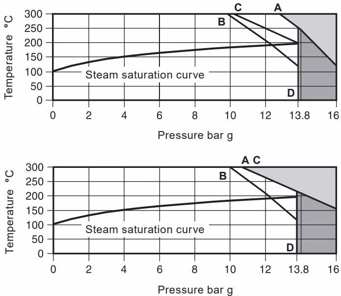
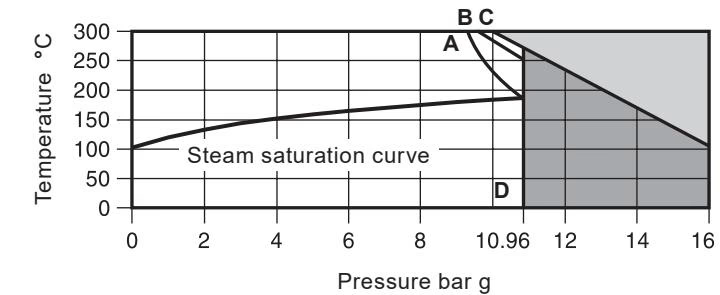
The product must not be used in the shaded region. A-D applies to flanged PN16, B-D to flanged JIS/KS 10, and C-D to flanged ANSI 150. The product is safe for use under full vacuum conditions.
| Condition | MFP14 | MFP14S | MFP14SS |
|---|---|---|---|
| Maximum motive inlet pressure (steam, air, or gas) | 13.8 bar g | 13.8 bar g | 10.96 bar g |
| PMA Maximum allowable pressure | 16 bar g at 120 C | 16 bar g at 120 C | 16 bar g at 93 C |
| TMA Maximum allowable temperature | 300 C at 12.8 bar g | 300 C at 10.8 bar g | 300 C at 9.3 bar g |
| Minimum allowable temperature | 0 C | 0 C | 0 C |
| PMO Maximum operating pressure for saturated steam service | 13.8 bar g at 198 C | 13.8 bar g at 198 C | 10.96 bar g at 188 C |
| TMO Maximum operating temperature for saturated steam service | 198 C at 13.8 bar g | 198 C at 13.8 bar g | 188 C at 10.96 bar g |
Total lift or backpressure, meaning static head plus pressure in the return system, must be below the motive fluid inlet pressure to allow capacity to be achieved. Calculate it as: Height (H) in metres x 0.0981 + return line pressure (bar g) + downstream piping friction pressure drop (bar), with friction calculated at the lesser of six times actual condensate rate or 30,000 litres/h.
Recommended filling head above the pump: 0.30 m
Minimum filling head required: 0.15 m with reduced capacity
Standard pump operates with liquids of specific gravity: 1 down to 0.8
| Data | DN80 x DN50 | DN50 | DN40 and DN25 |
|---|---|---|---|
| Pump discharge per cycle | 19.3 litres | 12.8 litres | 7 litres |
| Steam consumption | 20 kg/h maximum | 20 kg/h maximum | 16 kg/h maximum |
| Air consumption (free air) | 5.6 dm3/s maximum | 5.6 dm3/s maximum | 4.4 dm3/s maximum |
| Temperature limits (ambient) | -10 C to 200 C | -10 C to 200 C | -10 C to 200 C |
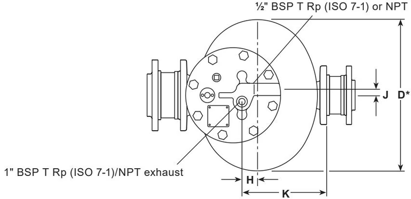
| Size | A JIS/KS PN | ANSI | B | C | D* | E | F | G | H | J | K | L | Pump only kg | Including check valves and flanges kg |
|---|---|---|---|---|---|---|---|---|---|---|---|---|---|---|
| DN25 | 410 | - | 305 | 507.0 | - | 68 | 68 | 480 | 13 | 18 | 165 | Ø280 | 51 | 58 |
| DN40 | 440 | - | 305 | 527.0 | - | 81 | 81 | 480 | 13 | 18 | 165 | Ø280 | 54 | 63 |
| DN50 | 557 | 625 | 420 | 637.5 | - | 104 | 104 | 580 | 33 | 18 | 245 | Ø321 | 72 | 82 |
| DN80 x DN50 | 573 | 645 | 420 | 637.5 | 430 | 119 | 104 | 580 | 33 | 18 | 245 | 342 | 88 | 98 |
* Dimension D only applies to the DN80 x DN50 pump which has an oval body. The DN25, DN40, and DN50 are round bodied, therefore dimension L is sufficient.
Motive inlet: 1/2" BSP T Rp (ISO 7-1) or NPT steam, compressed air, or gas inlet
Exhaust: 1" BSP T Rp (ISO 7-1) / NPT exhaust
Considering inlet pressure, backpressure, and filling head conditions, select the pump size which meets the capacity requirements of the application.
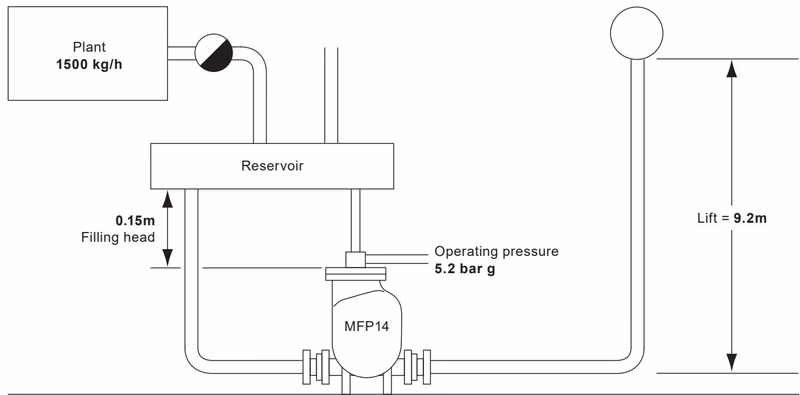
1500 kg/h5.2 bar g9.2 m1.7 bar g0.15 mIt is strongly recommended that the maximum motive/backpressure differential is between 2 and 4 bar g.
First calculate the total effective lift against which condensate must be pumped:
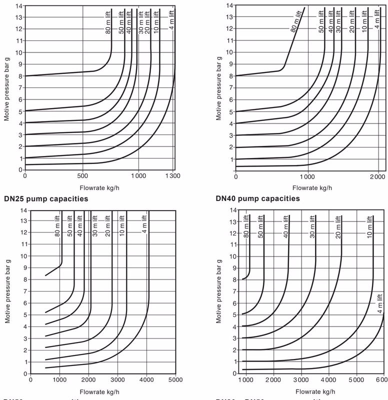
9.2 m1.7 bar g1.7 / 0.0981 = 17.3 m9.2 + 17.3 = 26.5 mNow plot the known data on the graph:
5.2 bar g motive pressure.26.5 m lift.2400 kg/h.Because the filling head is 0.15 m rather than 0.30 m, the capacity must be corrected by the appropriate multiplying factor.
| Filling head m | DN25 | DN40 | DN50 | DN80 x DN50 |
|---|---|---|---|---|
| 0.15 | 0.90 | 0.75 | 0.75 | 0.80 |
| 0.30 | 1.00 | 1.00 | 1.00 | 1.00 |
| 0.60 | 1.15 | 1.10 | 1.20 | 1.05 |
| 0.90 | 1.35 | 1.25 | 1.30 | 1.15 |
Final pump selection in this example is DN50. The corrected capacity is 0.75 x 2400 = 1800 kg/h, which comfortably handles a condensate load of 1500 kg/h.
| Pump size | 10% | 20% | 30% | 40% | 50% | 60% | 70% | 80% | 90% |
|---|---|---|---|---|---|---|---|---|---|
| DN25 | 1.20 | 1.25 | 1.30 | 1.35 | 1.40 | 1.43 | 1.46 | 1.50 | 1.53 |
| DN40 | 1.20 | 1.25 | 1.30 | 1.35 | 1.40 | 1.43 | 1.46 | 1.50 | 1.53 |
| DN50 | 1.02 | 1.05 | 1.08 | 1.10 | 1.15 | 1.20 | 1.27 | 1.33 | 1.40 |
| DN80 x DN50 | 1.02 | 1.05 | 1.08 | 1.10 | 1.15 | 1.20 | 1.27 | 1.33 | 1.40 |
If you are in doubt about pump size or operating conditions are unusual, Spirax Sarco recommends providing the following data:
For full details see Installation and Maintenance Instructions IM-P136-03 supplied with the product.
To achieve rated capacity, the pump must be installed with check valves as supplied by Spirax Sarco. Use of substitute check valves may affect performance.
Automatic pumps shall be Spirax Sarco type MFP14 with SG iron bodies and flanged or screwed connections. They shall have stainless steel valve and float assemblies, and a stainless steel disc check valve on the condensate inlet and outlet connections. They shall have screwed steam/compressed air inlet and exhaust connections.
Ordering example: 1 off Spirax Sarco DN50 MFP14 automatic pump having flanged EN 1092 PN16 connections with BSP T Rp (ISO 7-1) motive fluid connections, complete with check valves and 2" BSP screwed boss flanges.
No spare parts are available other than those listed below.
| Available spare | Part number reference |
|---|---|
| Cover gasket | 2 |
| Float | 7 |
| Inlet / outlet check valve (each) | 12 |
| Cover and internal mechanism assembly | 1, 2, 7 complete |
| Valve set, inlet and exhaust valves and seats | 16, 17, 18, 19, 20, 21 |
| Spring shaft kit, two spring assemblies including anchors and two shafts plus nuts and washers for rear shaft | 10 |
Always order spares using the description given above and state the pump model and size.