


PN16

TLV FJ32-B QuickTrap® free float steam trap with built-in bimetal automatic air vent. Designed for superheated or saturated steam mains and branches.
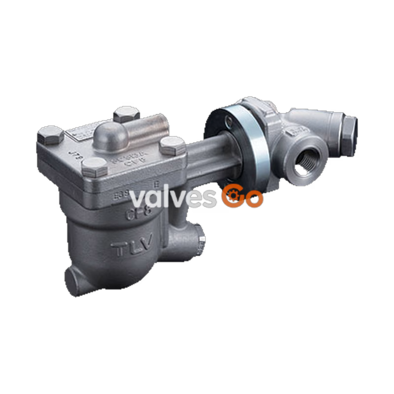
The TLV FJ32-B QuickTrap® is a free float steam trap with a built-in bimetal automatic air vent. It uses a two-bolt flange and three-point seating for a precision-ground float, which increases heating efficiency and reduces maintenance manpower. The two-bolt flange allows the trap to be installed in either horizontal or vertical piping.
This free float steam trap is suitable for steam mains or branches for superheated or saturated steam and tracing lines, where extremely small amounts of condensate are generated. It automatically discharges condensate at slightly lower than saturation temperature. The built-in automatic air vent rapidly discharges large amounts of condensate and air at startup, significantly reducing start-up time.
1. Air and Cold Condensate Discharge at Startup At startup, before steam is supplied, the system is cold and the bimetal plate is flexed downward, keeping the air vent valve open. This allows for the rapid discharge of air through the vent and cold condensate through the orifice when steam is first supplied.
2. Condensate Discharge After the discharge of initial air and cold condensate, the heat of the inflowing steam and condensate cause the bimetal plate to flex upward, closing the air vent valve. The rising condensate level causes the float to rise due to buoyancy, opening the orifice and allowing condensate to be discharged.
3. Discharge of Large Quantities of Condensate Increases in the condensate inflow rate cause the condensate level in the trap to rise. The float consequently rises and enlarges the opening of the orifice, allowing more condensate to be discharged.
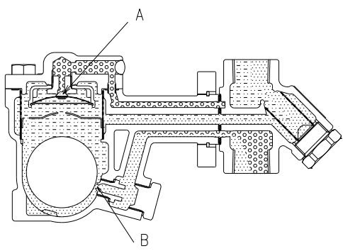
4. Closed Position When the condensate flow rate decreases, the float falls as condensate is discharged, closing off the orifice. A water seal is maintained at all times over the orifice to prevent steam loss.
WARNING
Install properly and DO NOT use this product outside the recommended operating pressure, temperature and other specification ranges. DO NOT use this product in excess of the maximum operating pressure differential. Use only under conditions in which no freeze-up will occur.
The specifications displayed on each nameplate apply only to the unit on which it is mounted. When a trap unit is installed on a connector unit and the PMA/TMA and/or PMO/TMO values displayed on the two nameplates differ, the specifications for the assembled products are restricted to the lower values.
Trap Unit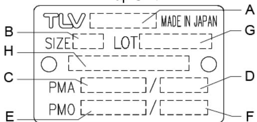
Connector Unit (mounted only on F46)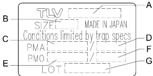
| A | Model |
| B | Nominal Diameter |
| C | Maximum Allowable Pressure (PMA)* |
| D | Maximum Allowable Temperature (TMA)* |
| E | Maximum Differential Pressure (PMX) |
| F | Maximum Operating Temperature (TMO) |
| G | Production Lot No. |
| H | Valve No.** |
*Maximum allowable pressure (PMA) and maximum allowable temperature (TMA) are PRESSURE SHELL DESIGN CONDITIONS, NOT OPERATING CONDITIONS. **Valve No. is displayed for products with options.
The FJ32-B QuickTrap employs connector unit F46 and is not compatible with QuickTrap models using connector unit F46J. The J32-B trap unit is compatible with trap stations (V1/V2/V1P/V2P Series) and Quick Station QS10, and can also be installed on connector unit F32.
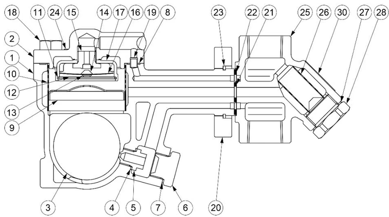
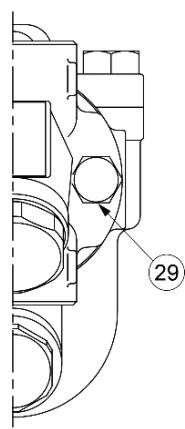
| No | Part Name | Trap Unit* | Connector Unit** |
|---|---|---|---|
| 1 | Trap Body | ✓ | |
| 2 | Cover | ✓ | |
| 3 | Float | ✓ | |
| 4 | Orifice Gasket | ✓ | |
| 5 | Orifice | ✓ | |
| 6 | Orifice Plug | ✓ | |
| 7 | Orifice Plug Gasket | ✓ | |
| 8 | Cover Gasket | ✓ | |
| 9 | Float Cover | ✓ | |
| 10 | Screen | ✓ | |
| 11 | Spring Clip | ✓ | |
| 12 | Screen | ✓ | |
| 13 | Spring Clip | ✓ | |
| 14 | Air Vent Valve Plug | ✓ | |
| 15 | Air Vent Valve Seat | ✓ | |
| 16 | Bimetal | ✓ | |
| 17 | Bimetal Case | ✓ | |
| 18 | Cover Bolt | ✓ | |
| 19 | Connector | ✓ | |
| 20 | Connector Flange | ✓ | |
| 21 | Inner Connector Gasket | ✓ | ✓ |
| 22 | Outer Connector Gasket | ✓ | ✓ |
| 23 | Connector Body | ✓ | |
| 24 | Screen | ✓ | |
| 25 | Screen Holder Gasket | ✓ | |
| 26 | Screen Holder | ✓ | |
| 27 | Connector Bolt | ✓ |
*J32-B **F46
Before installing the product, blow out the inlet piping to remove any piping scraps, dirt and oil. Close the inlet valve after blowdown. Install the connector body so that the arrow is pointing in the direction of flow.
The connector body has no restrictions on installation orientation except for the following conditions: the flange face (for connecting to the trap unit) must be in the vertical plane, and the trap unit must be installed with the nameplate facing upwards. The trap unit must be inclined no more than 5° horizontally and front-to-back.
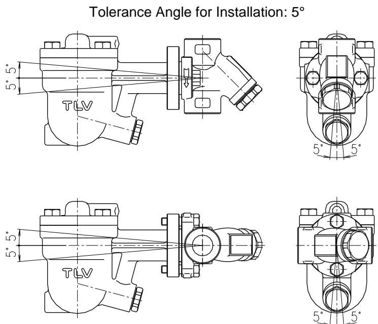
Installation Examples: Horizontal Piping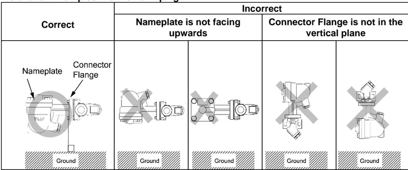
Installation Examples: Vertical Piping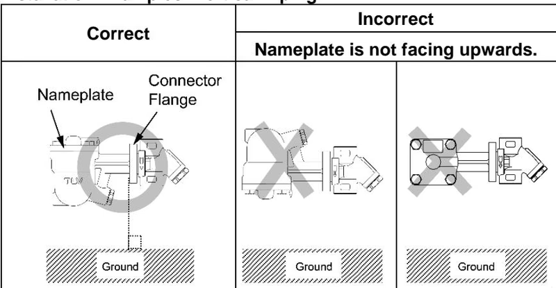
Note for Screwed Connection
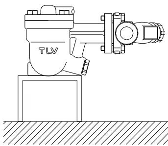
When products with screwed connections are installed on horizontal piping, there is a danger that the weight of the trap unit will cause the connector body to rotate on the pipe, putting the trap mechanism out of the horizontal plane. Tighten the screws securely. If the product is affected by vibrations, it is recommended that the trap unit should be supported to prevent rotation.
A visual inspection of the following items should be done on a daily basis to determine whether the product is operating properly.
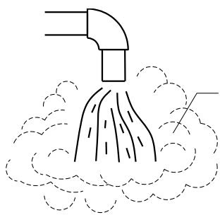
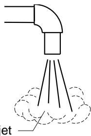
Flash Steam vs Live Steam Leakage Flash steam (normal): White jet containing water droplets. Live steam leakage (abnormal): Clear, slightly bluish jet.
With Drain Plug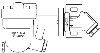
With Blowdown Valve (TLV-BD2) The BD2 blowdown valve, installed in the screen area of the connector body, uses the trap's internal pressure to blow any condensate, steam, dirt or scale accumulated around the screen area out to atmosphere.




