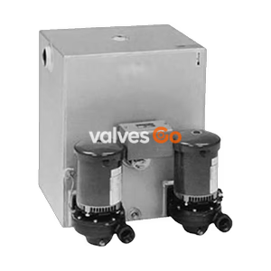
3450 RPM Motors

TLV GT10L compact mechanical pump with built-in steam trap for condensate removal and recovery. Handles high-temperature condensate without cavitation.
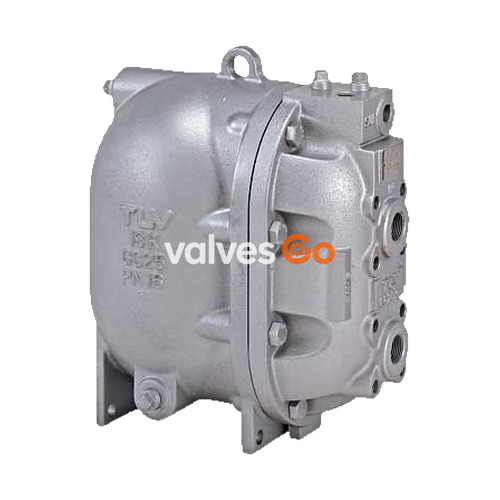
TLV GT10L is a compact mechanical pump with a built-in steam trap designed for a wide range of applications, including the drainage of low-capacity heat exchangers, flash steam recovery systems, and reservoirs that often operate under vacuum conditions. The PowerTrap series is used to discharge liquid from vacuum-pressure or low-pressure areas to high-pressure areas, or from lower to higher elevations.
The GT model features an additional steam trap function, making it suitable for use in instances in which the inlet pressure may alternately be lower than or higher than the outlet pressure. The GP model is a mechanical pump without the built-in trap.
WARNING
Install properly and DO NOT use this product outside the recommended operating pressure, temperature, and other specification ranges. Improper use may result in such hazards as damage to the product or malfunctions which may lead to serious accidents.
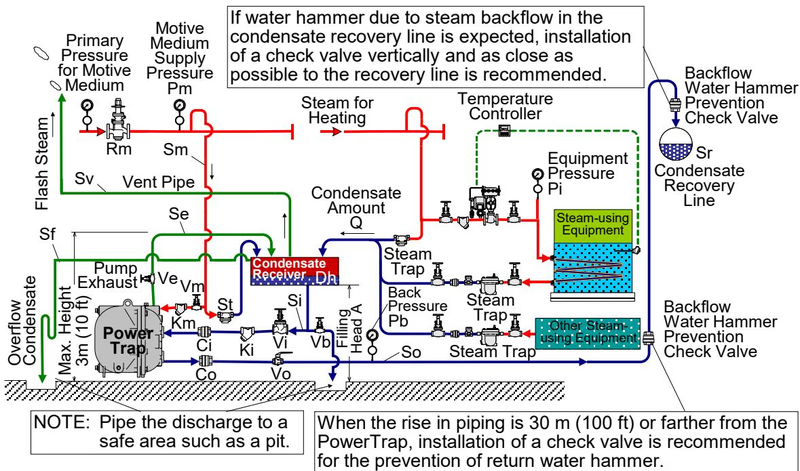
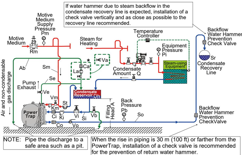
There are two types of delivery systems (piping methods): the closed system and the open system. Use of the GT model or the GP model is determined by the type of system.
| Type of System | Closed System | Open System |
|---|---|---|
| Benefits | - No need for external steam trap (GT model features built-in trap) - No flash steam discharge - Small reservoir - Use with vacuum equipment possible | - Collection of condensate from multiple equipment possible - Can be used where trap is lower than receiver |
| Notes | - Only one piece of equipment possible per system - Equipment has minimum height requirement to ensure condensate flows naturally | - Separate steam trap required for each piece of equipment - Requires venting pipe to discharge flash steam to atmosphere |
| Model | GT10L / GT14L / GT14M (Mechanical pump with built-in trap) | GP10L / GP14L / GP14M (Mechanical pump) |

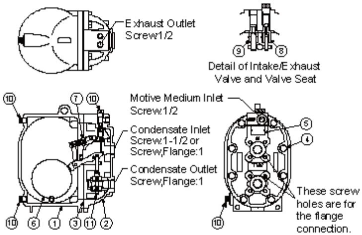
| No. | Part Name | No. | Part Name | No. | Part Name |
|---|---|---|---|---|---|
| 1 | Body | 5 | Nameplate | 9 | Exhaust Valve Unit |
| 2 | Cover | 6 | Float | 10 | Plug |
| 3 | Cover Gasket | 7 | Snap-action Unit | 11 | Trap Unit (GT10L only) |
| 4 | Cover Bolt | 8 | Intake Valve Unit |
INFO
In closed system applications, the motive medium must be compatible with the liquid being pumped. If a non-condensable gas such as air or nitrogen is used as the motive medium, please consult TLV for assistance.
Explore similar products in our catalog