ENP Nickel Plating

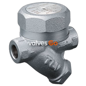
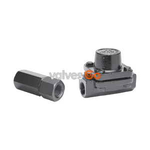
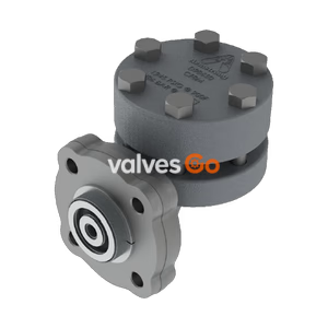
TLV HR260A PowerDyne thermodynamic disc trap for supercritical steam service. Features an inline replaceable module, air jacket, and max operating pressure of 260 barg at 550°C.
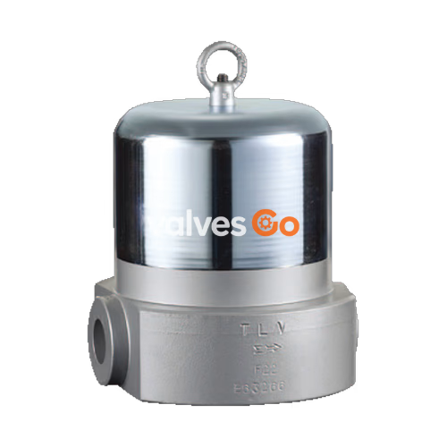
The TLV HR260A is a PowerDyne thermodynamic disc trap designed for supercritical service in high-pressure steam mains and turbines. It features an air-jacketed design that reduces radiant heat loss, minimizing no-load cycling and extending the service life of the trap. The HR260A is capable of handling a maximum operating pressure of 260 barg (26 MPaG) and a maximum operating temperature of 550 °C, making it suitable for demanding power plant applications worldwide.
DANGER
Indicates an urgent situation that poses a threat of death or serious injury.
WARNING
Indicates that there is a potential threat of death or serious injury.
CAUTION
Indicates that there is a possibility of injury, or equipment/product damage.
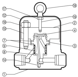
| No. | Description | Material | DIN* | ASTM/AISI* |
|---|---|---|---|---|
| 1 | Body | Alloy Steel A182 F22 Cl.3 / Alloy Steel (9%Cr - 1%Mo) | 1.7380 / 1.4903 | - / - |
| 2 | Cover | Stainless Steel SUS420J2 | 1.4031 | AISI420 |
| 3 | Module Valve Seat | Stainless Steel SUS440C | 1.4125 | AISI440C |
| 4 | Disc | Stainless Steel SUS440C | 1.4125 | AISI440C |
| 5 | Eye Nut | Carbon Steel SS400 | 1.0037 | A6 |
| 6 | Spacer | Carbon Steel SS400 | 1.0037 | A6 |
| 7 | Module Gasket | Graphite/Stainl. Stl. SUS309S+Cb | -/1.4833 | -/AISI309S+Cb |
| 8 | Module Gasket | Graphite/Stainl. Stl. SUS309S+Cb | -/1.4833 | -/AISI309S+Cb |
| 9 | Screen inside/outside | Stainless Steel SUS430/304 | 1.4016/4301 | AISI430/304 |
| 10 | Body Bolt | Alloy Steel SNB16 | 1.7711 | A193 Gr.B16 |
| 11 | Cover Nut | Alloy Steel SNB7 | 1.7225 | A193 Gr.B7 |
| 12 | Cap | Carbon Steel SPCC | 1.0330 | A109 |
| 13 | Guide Pin | Stainless Steel SUS304 | 1.4301 | AISI304 |
| 14 | Nameplate | Stainless Steel SUS304 | 1.4301 | AISI304 |
| 15 | Hexagon Nut | Carbon Steel SS400 | 1.0037 | A6 |
(M) maintenance parts, (R) repair parts available in replacement kits.
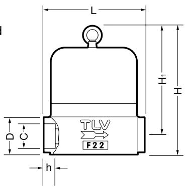
| DN | L (mm) | H (mm) | H1 (mm) | φD (mm) | φC (mm) | h (mm) | Weight (kg) |
|---|---|---|---|---|---|---|---|
| 15 | 160 | 208 | 179 | 53.5 | 21.8 | 14 | 18 |
| 20 | 160 | 208 | 179 | 53.5 | 27.7 | 14 | 18 |
| 25 | 160 | 208 | 179 | 53.5 | 33.9 | 14 | 18 |
ASME B16.11-2005, other standards available. DN 20 dimensions based on regional specifications.
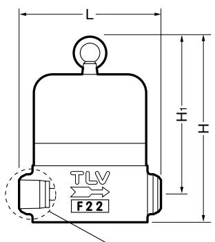
| DN | L (mm) | H (mm) | H1 (mm) | φD (mm) | φD1 (mm) | φd (mm) | h (mm) | Weight (kg) |
|---|---|---|---|---|---|---|---|---|
| 15 | 165 | 208 | 179 | 28 | 22 | 16 | 20 | 18 |
| 25 | 165 | 208 | 179 | 40 | 35 | 27 | 20 | 18 |
DIN 3239 Form C (PN250), other standards available.
Check to make sure that the pipes connected to the trap have been installed properly.
| Requirement | Incorrect Condition |
|---|---|
| Install a catchpot with the proper diameter. | Diameter is too small. |
| Make sure the flow of condensate is not obstructed. | Diameter is too small and inlet protrudes into pipe. |
| To prevent rust and scale from flowing into the trap, connect the inlet pipe 25 - 50 mm (1 - 2 in) above the base of the T-pipe. | Rust and scale flow into the trap with the condensate. |
| When installing on the blind end, make sure nothing obstructs the flow of condensate. | Condensate collects in the pipe. |
IMPORTANT START-UP PROCEDURE
To ensure proper operation, slowly open the inlet valve slightly. Initially OPEN THE VALVE ONLY 1/32 TURN in order to supply steam to the trap very slowly, then WAIT FOR AT LEAST 30 SECONDS for air to vent before fully opening the inlet valve.
A visual inspection can be carried out to aid in determining the necessity for immediate maintenance or repair, if the trap is open to atmosphere. If the trap does not discharge to atmosphere, use diagnostic equipment such as TLV TrapMan (within its pressure and temperature measuring range).
| Status | Description |
|---|---|
| Normal | Condensate is discharged in a short blast followed by a longer period of no drainage. During the discharge, flash steam may be seen. A small amount of flash steam may be visible after the discharge. |
| Blocked | No condensate is discharged. The trap is quiet and makes no noise. The surface temperature of the trap is low. |
| Blowing | Live steam continually flows from the outlet, and there is a continuous metallic sound. |
| Steam Leakage | Live steam is discharged through the trap outlet together with condensate, accompanied by a high-pitched sound. |
| Chattering | The trap does not close properly. Steam is discharged from the trap in short rapid bursts. |
(When conducting a visual inspection, flash steam is sometimes mistaken for steam leakage. For this reason, the use of a steam trap diagnostic instrument is highly recommended.)
Operational inspections should be performed at least twice per year, or as called for by trap operating conditions. Steam trap failure may result in temperature drop in the equipment, poor product quality or losses due to steam leakage.
WARNING
Before attempting to open the trap, close the inlet and outlet isolating valves and wait until the trap has cooled completely. Failure to do so may result in burns.
| Part | Inspection Item |
|---|---|
| Sealing surfaces | Check for damage or dirt on the sealing surfaces |
| Screen | Check for clogging or corrosion damage |
| Disc | Check for wear and damage, scratches, on the surface where it contacts the valve seat, and dirt or oil film |
| Module valve seat | Check discharge channel and grooves for rust and scale inside |
| Body, Cover | Check inside for erosion, dirt, grease, rust or scale |
| Part | Disassembly | Reassembly |
|---|---|---|
| Cap / Eye Nut | Remove the eye nut and then the cap. | Adjust length of spacer, if necessary. |
| Cover nut / Cover | Use a socket wrench to remove nuts at diagonal positions sequentially. Apply liquid penetrant for at least 5 minutes to loosen the nuts, if necessary. Lift up and remove cover. | Tighten nuts at diagonal position sequentially after having applied antiseize to the threads. It is recommended to use new nuts for the assembly. Tighten to the proper torque. |
| Module gasket (large) | Remove the gasket and clean the sealing surfaces. | Replace with a new gasket even if no damage can be seen. |
| Disc | Remove, being careful not to scratch the lapped surface. | Make sure that the seat surface (the lapped side with groove) is facing down, toward the valve seat. |
| Module valve seat and Guide pin | Remove from the body. | Insert the guide pin into the hole in the body and make sure it fits properly into the respective hole of the module valve seat. |
| Module gasket (small) | Remove the gasket and clean the sealing surfaces. | Replace with a new gasket even if no damage can be seen. |
| Screen | Be careful not to bend the screen. | Be careful not to bend the screen. |
| Part | Torque N·m (lb-ft) | Distance Across Flats (mm) |
|---|---|---|
| Cover nut HR260A | 280 (205) | 27 (1 1/16 in) |
If the expected performance is unachievable after installation of the trap, check the following points for appropriate corrective measures.
| Problem | Cause | Remedy |
|---|---|---|
| No condensate is discharged (blocked) or discharge is poor | Screen is clogged with rust or scale | Clean |
| Disc is sticking to valve seat (due to oil, etc.) | Clean | |
| Steam-locking has occurred | Perform a bypass blow-down, or close the trap inlet valve and allow the trap to cool. Piping correction may also be required. | |
| Trap capacity is insufficient | Change to trap of suitable capacity | |
| Differential pressure is low | Study inlet/outlet pressure, including rise in outlet pipe | |
| Steam leakage or blowing (from valve seat) | Valve closure is obstructed by scale, etc. | Clean or replace screen |
| Disc or valve seat is worn | Replace worn parts | |
| Back pressure exceeds allowable value | Use within pressure range | |
| Trap is being used below minimum operating pressure | Use within pressure range | |
| Disc is sticking to top of cover (due to oil, etc.) | Clean | |
| Valve chattering (Leakage) | Foreign matter or oil film on disc or valve seat | Clean |
| Scratches on disc or valve seat | Replace disc or module valve seat | |
| Disc or valve seat is worn | Replace disc or module valve seat | |
| Leakage from a location other than valve seat | Bypass valve is damaged or open | Replace or close bypass valve |
| Cover is loose or module gaskets are damaged | Tighten cover or replace module gaskets |
Explore similar products in our catalog