


PN16

TLV J5S-X free float steam trap with thermostatic air vent (X-element). Designed for tracer lines, heaters, and heat exchangers up to 2.1 MPaG (300 psig).
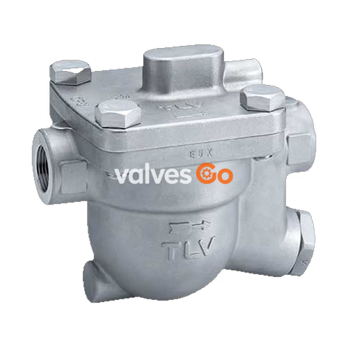
The TLV J5S-X free float steam trap with thermostatic air vent (X-element) is suitable for a wide range of applications up to 2.1 MPaG (300 psig), such as tracer lines, unit and process heaters, heating coils, and heat exchangers. The trap discharges condensate continuously and automatically, at a temperature slightly lower than saturation temperature.
Related Models
The source manual also covers related models J3S-X and J6S-X (up to 2.1 MPaG), as well as J3S-X S1 and J3S-X S2 which are designed for rubber vulcanizer applications up to 1.4 MPaG (200 psig).
DANGER
NEVER apply direct heat to the float. The float may explode due to increased internal pressure, causing accidents leading to serious injury or damage to property and equipment.
WARNING
Install properly and DO NOT use this product outside the recommended operating pressure, temperature and other specification ranges. DO NOT use this product in excess of the maximum operating pressure differential.
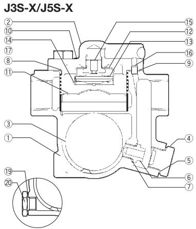
Key components include the Body, Cover, Float, Orifice Plug, Orifice, X-element, and Air Vent Valve Seat. (Refer to the product nameplate for detailed specifications. Maximum allowable pressure (PMA) and maximum allowable temperature (TMA) are pressure shell design conditions, not operating conditions.)
TIP
Installation, inspection, maintenance, repairs, disassembly, adjustment and valve opening/closing should be carried out only by trained maintenance personnel.
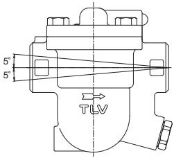
Allowable Inclination
| Requirement | Correct | Incorrect |
|---|---|---|
| Catchpot | Install a catchpot with the proper diameter. | Diameter is too small. |
| Condensate Flow | Make sure the flow of condensate is not obstructed. | Diameter is too small and inlet protrudes into pipe. |
| Inlet Pipe Connection | To prevent rust and scale from flowing into the trap, connect the inlet pipe 25-50 mm (1-2 in.) above the base of the T-pipe. | Rust and scale flow into the trap with the condensate. |
| Blind End Installation | When installing on the blind end, make sure nothing obstructs the flow of condensate. | Condensate collects in the pipe. |
Operational inspections should be performed at least twice per year, or as called for by trap operating conditions. Steam trap failure may result in a temperature drop in the equipment, poor product quality, or losses due to steam leakage.
Tightening Torque (J5S-X)
| Part | Torque N·m (lbf·ft) | Distance Across Flats mm (in) |
|---|---|---|
| Cover Bolt | 80 (59) | 22 (7/8) |
| Air Vent Valve Seat | 35 (26) | 19 (3/4) |
| Orifice Plug | 180 (130) | 38 (1 1/2) |
| Orifice | 140 (100) | 17 (21/32) |
| Drain Plug (Option) | 35 (26) | 21 (13/16) |
| Status | Description |
|---|---|
| Normal | Condensate is discharged continuously with flash steam and the sound of flow can be heard. If there is very little condensate, there is almost no sound of flow. |
| Blocked | No condensate is discharged. The trap is quiet and makes no noise, and the surface temperature of the trap is low. |
| Blowing | Live steam continually flows from the outlet and there is a continuous metallic sound. |
| Steam Leakage | Live steam is discharged through the trap outlet together with the condensate and there is a high-pitched sound. |
(When conducting a visual inspection, flash steam is sometimes mistaken for steam leakage. For this reason, the use of a steam trap diagnostic instrument is highly recommended.)




