Repairable

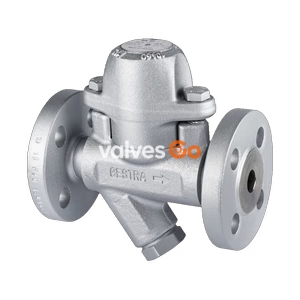
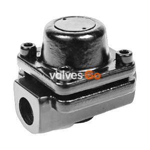
TLV LV8 and LV8-HC stainless steel balanced pressure thermostatic steam traps. Designed for medium capacity applications up to 2.1 MPaG, tracer lines, vessels, and heaters.
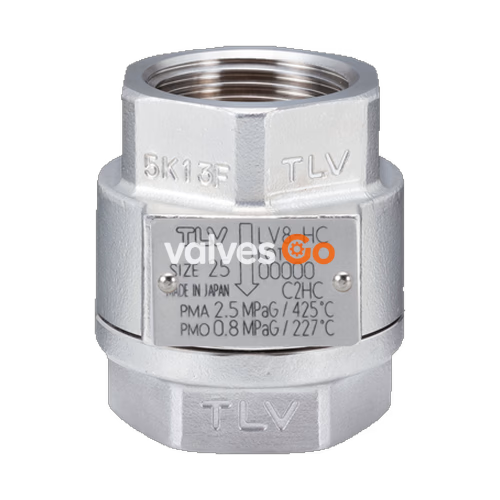
TLV LV8 and LV8-HC are stainless steel balanced pressure thermostatic steam traps. The LV Series steam traps can be used without adjustment for medium capacity applications up to 0.5, 0.8, 1.3, or 2.1 MPaG (75, 115, 185, or 300 psig). These models are suitable for steam-using equipment that discharges condensate at temperatures slightly below saturation temperature, such as tracer lines, vessels, and heaters.
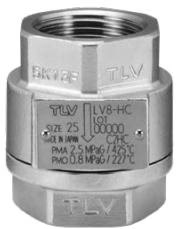
The LV8 and LV8-HC are constructed primarily of stainless steel and are designed with a fail-open characteristic.
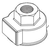
| No. | Description | Replacement Part |
|---|---|---|
| 1 | Body (Stainless Steel) | |
| 2 | Cover (Stainless Steel) | |
| 3 | X-element | √ |
| 4 | Valve Seat** | √ |
| 5 | Screen | √ |
| 6 | Nameplate | |
| 8 | Cover Gasket | √ |
*Note: For the LV8 and LV8-HC, the valve seat is pressed into the cover and is not replaceable. These models do not feature a spring clip to secure the X-element.
WARNING
Install properly and do not use this product outside the recommended operating pressure, temperature, and other specification ranges.
A visual inspection can help determine if immediate maintenance or repair is necessary.
| Status | Description |
|---|---|
| Normal | Condensate is discharged intermittently with flash steam and the sound of flow can be heard. |
| Blocked | No condensate is discharged. The trap is quiet and makes no noise. The surface temperature of the trap is low. |
| Blowing | Live steam continually flows from the outlet and there may be a high-pitched whistling sound. |
| Steam Leakage | Live steam is discharged through the trap outlet together with the condensate and there may be a high-pitched whistling sound. |
Operational inspections should be performed at least twice per year. Before attempting to open the trap, close the inlet and outlet isolation valves and wait until the trap has cooled to room temperature.
Parts Inspection:
Tightening Torque (Cover): For LV8 and LV8-HC (Stainless Steel), use a tightening torque of 120 N·m (88 lbf·ft). Distance across flats is 27 mm for 8 to 15 (1/4 to 1/2) connections and 41 mm for 20 to 25 (3/4 to 1) connections.
Explore similar products in our catalog