
Dry Steam Discharge

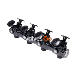
TLV M4, M8, and M12 forged carbon steel manifolds incorporate maintenance-free bellows-sealed valves at each station connection. When used as condensate collection manifolds, these products consolidate steam trap locations at lower installation heights, making traps more accessible and easier to install, isolate, test, and troubleshoot.
CAUTION
| Model | M4 |
|---|---|
| Steam Outlet / Condensate Inlet | 4 per M4 unit |
| Connection | Socket Welded |
| Size | DN 15, 20 |
| Steam Inlet & Drain / Condensate Outlet & Blowdown | Socket Welded |
| Size | DN 40 |
| Maximum Operating Pressure (PMO) | 50 barg |
| Maximum Operating Temperature (TMO) | 400 °C |
Note: Maximum Allowable Pressure (PMA) is 57 barg. Maximum Allowable Temperature (TMA) is 425 °C.
Materials
| No. | Description | Material | DIN | ASTM/AISI |
|---|---|---|---|---|
| 1 | Body | Carbon Steel A105 | 1.0460 | - |
| 2 | Valve Bonnet | Carbon Steel A105 | 1.0460 | - |
| 3 | Valve Plug | Stainless Steel A276-304 + Stellite | - | - |
| 4 | Valve Seat | Stainless Steel A276-410 + Stellite | - | - |
| 5 | Valve Stem | Stainless Steel A276-410 | - | - |
| 6 | Bellows | Stainless Steel SUS316L | 1.4404 | AISI316L |
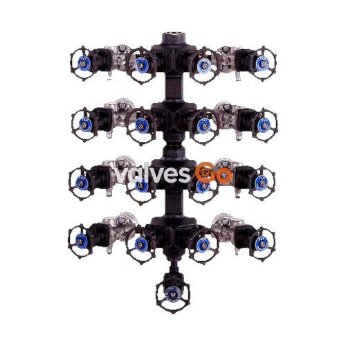
The M4 is a 4-way manifold (with four station connections, each with an individual valve unit). The model name reflects the amount of connections: the M8 is an 8-way, the M12 a 12-way manifold.
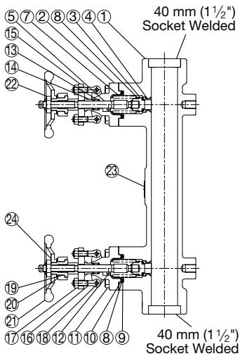 M4 (for steam/condensate)
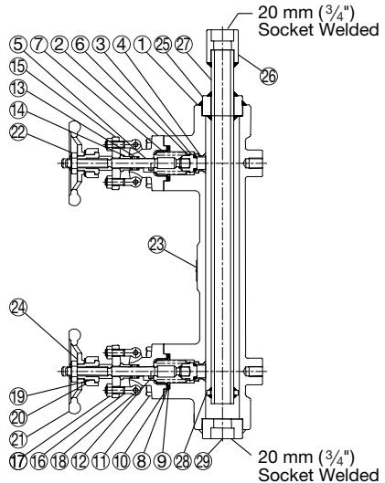 M4 with Inner Pipe (Option for condensate)
For Steam Manifolds: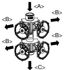 A: Steam Inlet | B: Station Connection - Steam Outlet
For Condensate Manifolds: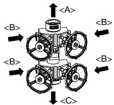 A: Condensate Outlet | B: Station Connection - Condensate Inlet | C: Blowdown Connection
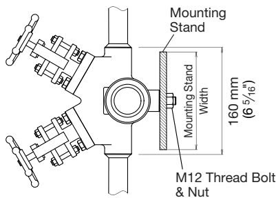
Screwed Connections
There may be clearance problems when installing traps and valves with threaded connections. To prevent obstructions, offset each line slightly. Install all short lines first, then longer lines.

| Part | Inspection Procedure |
|---|---|
| Gaskets | Check for warping and damage |
| Bellows | Check for cracking, warping or other damage |
| Valve Seat | Check for build-up, scratches or wear |
| Valve Plug | Check for build-up, scratches or wear |
| Body Interior | Check for build-up or scale |
Disassembly and Reassembly
| Part | During Disassembly | During Reassembly |
|---|---|---|
| Bonnet Bolt | Remove with a 12 mm socket wrench | Coat threads with anti-seize; tighten to 60 N·m torque |
| Valve Unit | Pull straight out being careful not to scratch plug or dent bellows | Insert plug into body, being careful not to dent bellows |
| Bonnet Gasket | Clean being careful not to scratch body seat | Replace with a new gasket |
| Problem | Cause | Remedy |
|---|---|---|
| Fluid leaks from the outlet when closed | Build-up on the valve seat or plug, or parts are scratched/damaged | Clean parts or replace the valve unit |
| Fluid leaks from the gland area | Build-up on the gland packing, or it is scratched/worn, or bellows damaged | Further tighten the gland nut, or replace with a new valve unit |
| Valve does not open/close or is stuck | Build-up on the valve seat or plug | Clean or replace part; apply grease to stem screw |
| Fluid leaks from the bonnet flange | Gasket deterioration or improper tightening torque | Replace gasket or tighten to 60 N·m |
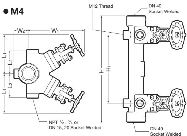
M4 Basic Manifold (mm)
| L1* | L2 | H | H1 | W1* | W2 | Weight (kg) |
|---|---|---|---|---|---|---|
| 135 | 80 | 390 | 250 | 185 | 48 | 17 |
| *At full open position |
Socket Welded Connections
| DN | φD (mm) | φC (mm) | h (mm) |
|---|---|---|---|
| 15 | 37 | 21.8 | 13 |
| 20 | 37 | 27.2 | 13 |
| 40 | 64 | 48.8 | 13 |
Steam manifolds (SM) include a bellows-sealed stop valve at the steam inlet, and an FS3 steam trap with a bellows-sealed stop valve at the drain. Condensate manifolds (CM) include bellows-sealed stop valves at both the condensate outlet and blowdown connections, and V1 trap stations at each inlet.
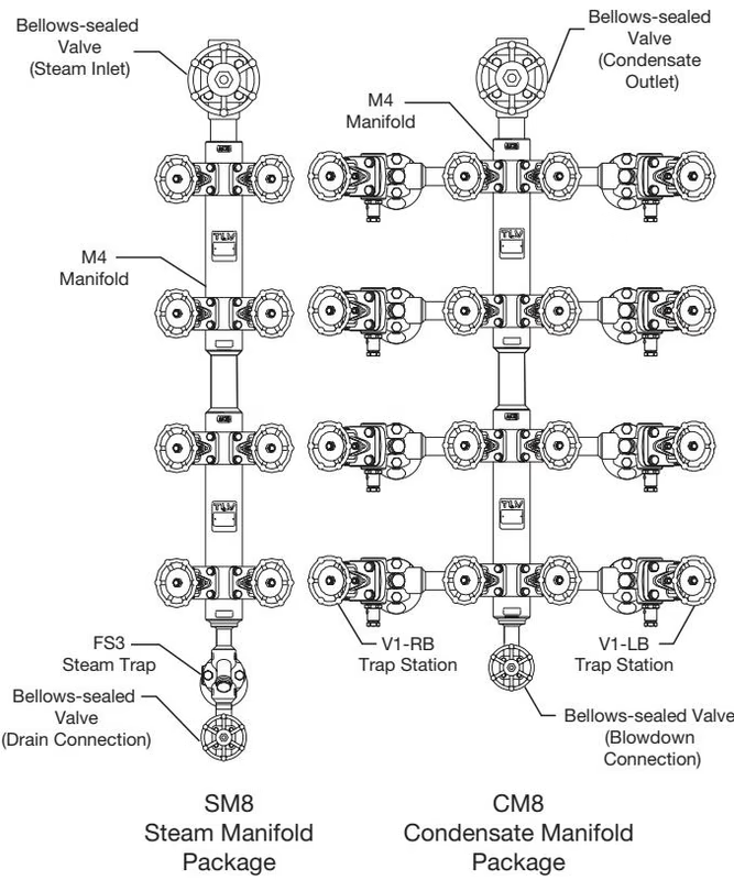
| Manifold Package | No. of Connections | Length (mm) | Height (mm) | Weight (kg) |
|---|---|---|---|---|
| SM4 | 4 | 160 | 890 | 37 |
| SM8 | 8 | 160 | 1390 | 54 |
| SM12 | 12 | 160 | 1890 | 70 |
| CM4 | 4 | 560 | 740 | 53 |
| CM8 | 8 | 560 | 1240 | 88 |
| CM12 | 12 | 560 | 1740 | 123 |