Cast Iron

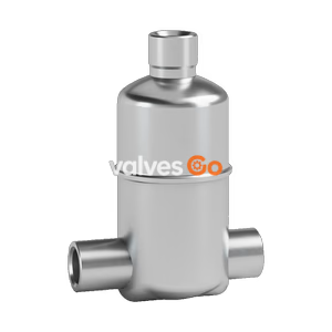
TLV SS1VG-R-M2 and SS1VG-M-M2 are stainless steel free float drain traps designed for air and inert gas systems. Featuring a precision-ground float, up to 21 barg max pressure, and a three-point seating design for reliable condensate removal.
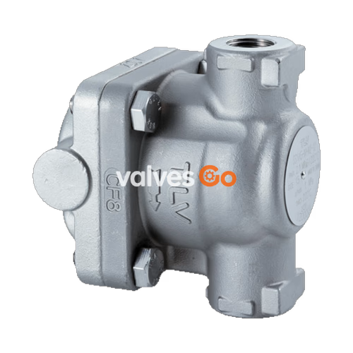
TLV SS1VG-R-M2 and SS1VG-M-M2 are stainless steel free float drain traps designed to automatically drain condensate from air and inert gas systems. The models feature a precision-ground float and three-point seating to ensure tight sealing. The SS1VG-R-M2 employs a rubber orifice for tight shut-off even under no-load conditions, while the SS1VG-M-M2 uses a metal orifice suitable for higher temperatures.
| Model | SS1VG-R-M2 (Rubber Orifice) | SS1VG-M-M2 (Metal Orifice) |
|---|---|---|
| Connection | Screwed, Socket Weld, Flanged | Screwed, Socket Weld, Flanged |
| Size | 1/2", 3/4", 1" (15, 20, 25 mm) | 1/2", 3/4", 1" (15, 20, 25 mm) |
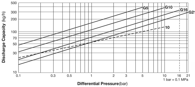
| Orifice No. | 10 | G5, G10, G16, G21 |
| Max Operating Pressure (PMO) | 10 barg | 5, 10, 16, 21 barg |
| Max Differential Pressure (ΔPMX) | 10 bar | 5, 10, 16, 21 bar |
| Max Operating Temperature (TMO) | 150 °C | 220 °C |
| Min Condensate Load for Tight Sealing | 0 kg/h | 0.5 kg/h |
| Applicable Fluid | Air, Inert Gases | Air, Inert Gases |
WARNING
DO NOT use this product in excess of the maximum operating pressure differential. Such use could make discharge impossible (blocked). Do not use for toxic, flammable or otherwise hazardous fluids.
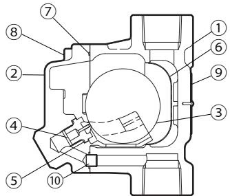
| No. | Description | Material | DIN | ASTM/AISI |
|---|---|---|---|---|
| 1 | Body | Cast Stainless Steel | 1.4312 | A351 Gr.CF8 |
| 2 | Cover | Cast Stainless Steel | 1.4312 | A351 Gr.CF8 |
| 3 | Float | Stainless Steel | 1.4404 | AISI 316L |
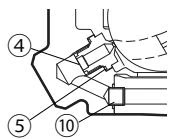
| 4 | Orifice (Rubber) | Fluorine Rubber FPM / Stainless Steel | -/1.4305 | D2000HK / AISI 303 |
| 4 | Orifice (Metal) | Stainless Steel SUS316L + Stellite | 1.4404 | AISI 316L |
| 5 | Orifice Gasket | Fluorine Resin PTFE | - | - |
| 6 | Screen | Stainless Steel | 1.4301 | AISI 304 |
| 7 | Cover Gasket | Fluorine Resin PTFE | - | - |
DANGER
NEVER apply direct heat to the float. The float may explode due to increased internal pressure, causing accidents leading to serious injury or damage to property and equipment.
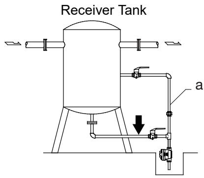
To prevent air binding and ensure air or gas can be displaced by incoming condensate, a pressure-balancing line should be installed between the product cover and the dry portion of the receiver tank when horizontal piping is used.
Explore similar products in our catalog