


PN16

The TLV SH3NL is a cast steel free float steam trap with three-point seating and thermostatic air venting, designed for high-pressure steam mains and turbines up to 45 barg and 425 °C.
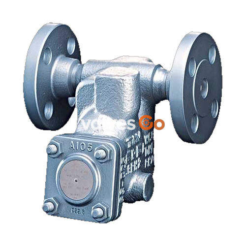
The TLV SH3NL is an inline repairable cast steel free float steam trap with a tight shut-off designed for the drainage of superheated or high-pressure steam mains and turbines. It features a self-modulating free float that provides continuous, smooth, low-velocity condensate discharge as loads vary. The precision-ground float, constant water seal, and three-point seating design ensure a steam-tight seal, even under no-load conditions. With only one moving part, the free float prevents concentrated wear and provides a long maintenance-free service life. A thermostatic air venting with a bimetal strip allows for fast start-up.
| Model | SH3NL |
|---|---|
| Connection | Socket Welded, Flanged |
| Size | DN 15, 20, 25 |
| Orifice No. | 14, 32, 45 |
| Maximum Operating Pressure (PMO) | 14, 32, 45 barg |
| Maximum Differential Pressure (ΔPMX) | 14, 32, 45 bar |
| Maximum Operating Temperature (TMO) | 425 °C |
WARNING
PRESSURE SHELL DESIGN CONDITIONS (NOT OPERATING CONDITIONS): Maximum Allowable Pressure (PMA): 45 barg Maximum Allowable Temperature (TMA): 425 °C Local regulations may restrict the use of this product to below the conditions quoted.
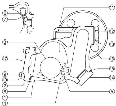
| No. | Description | Material | DIN | ASTM/AISI |
|---|---|---|---|---|
| 1 | Body | Cast Steel A216 Gr.WCB | 1.0619 | - |
| 2 | Cover | Carbon Steel A105 | 1.0460 | - |
| 3 | Float | Stainless Steel SUS316L | 1.4404 | AISI316L |
| 4 | Orifice | - | - | - |
| 5 | Orifice Gasket | Graphite/Stainl. Steel SUS316L | -/1.4404 | -/AISI316L |
| 6 | Air Vent Strip | Bimetal | - | - |
| 7 | Screw & Spring Washer | Stainless Steel SUS304 | 1.4301 | AISI304 |
| 8 | Cover Gasket | Graphite/Stainl. Steel SUS316L | -/1.4404 | -/AISI316L |
| 9 | Cover Bolt | Alloy Steel SNB7 | 1.7225 | A193 Gr.B7 |
| 10 | Cover Nut | Carbon Steel S45C | 1.0503 | AISI1045 |
| 11 | Screen | Stainless Steel SUS430 | 1.4016 | AISI430 |
| 12 | Screen Holder | Cast Stainl. Steel A351 Gr.CF8 | 1.4312 | - |
| 13 | Screen Holder Gasket | Soft Iron SUYP | 1.1121 | AISI1010 |
| 14 | Orifice Plug | Cast Stainl. Steel A351 Gr.CF8 | 1.4312 | - |
| 15 | Orifice Plug Gasket | Soft Iron SUYP | 1.1121 | AISI1010 |
| 16 | Socket | Carbon Steel S25C | 1.1158 | AISI1025 |
| 16 | Flange | Carbon Steel A105/Cast Steel A216 Gr.WCB | 1.0460/1.0619 | - |
| 17 | Nameplate | Stainless Steel SUS304 | 1.4301 | AISI304 |
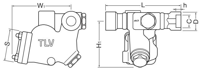
SH3NL Socket Welded (mm)
| DN | L | H1 | W1 | S | φD | φC | h | Weight (kg) |
|---|---|---|---|---|---|---|---|---|
| 15 | 200 | 125 | 160 | 83 | 32 | 21.8 | 12 | 8.5 |
| 20 | 200 | 125 | 160 | 83 | 38 | 27.2 | 14 | 8.5 |
| 25 | 200 | 125 | 160 | 83 | 47 | 33.9 | 14 | 8.5 |
SH3NL Flanged (mm)
| DN | L (150RF) | L (300RF) | L (600RF) | H1 | W1 | S | Weight (kg) |
|---|---|---|---|---|---|---|---|
| 15 | 202 | 202 | 202 | 125 | 160 | 83 | 9.0 |
| 20 | 202 | 202 | 202 | 125 | 160 | 83 | 9.6 |
| 25 | 202 | 202 | 202 | 125 | 160 | 83 | 10 |
(Weight is for Class 600 RF)
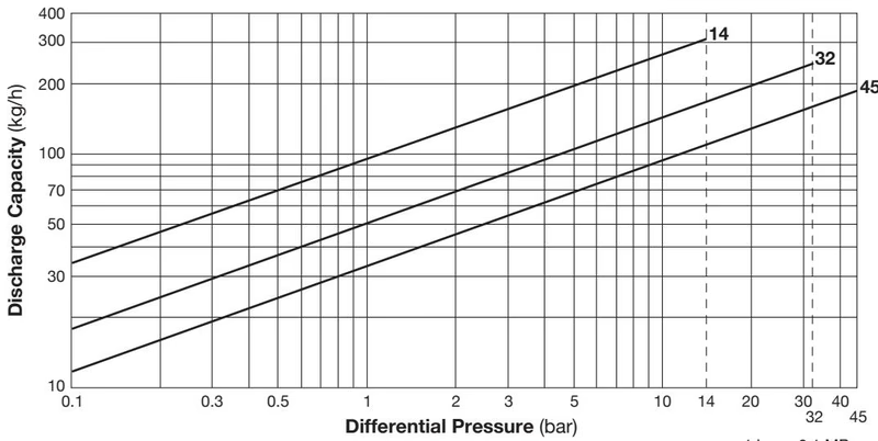
DANGER
DO NOT use traps under conditions that exceed maximum differential pressure, as condensate back up will occur!
Allowable Inclination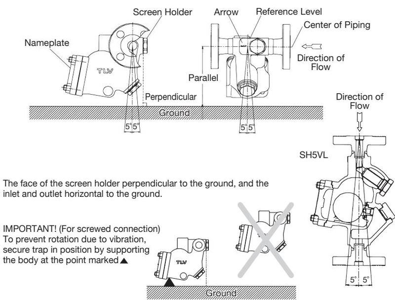
Operational inspections should be performed at least twice per year, or as called for by trap operating conditions. Steam trap failure may result in a temperature drop in the equipment, poor product quality or losses due to steam leakage.
DANGER
NEVER apply direct heat to the float. The float may explode due to increased internal pressure, causing accidents leading to serious injury or property and equipment damage.
Parts Inspection Procedure
| Part | Inspection Item |
|---|---|
| Body, Cover | Check inside for damage, dirt, grease, oil film, rust or scale |
| Gaskets | Check for warping or damage |
| Air Vent Strip | Check for damage |
| Screen | Check for clogging, corrosion or damage |
| Float | Check for deformation, damage, oil film or water inside |
| Orifice | Check for rust, scale, oil film, wear or damage |
Tightening Torque and Distance Across Flats (SH3NL)
| Part | Torque (N·m) | Distance Across Flats (mm) |
|---|---|---|
| Cover Nut | 60 | 17 |
| Orifice | 60 | 17 |
| Orifice Plug | 200 | 38 |
| Screen Holder | 200 | 38 |
| Screw | 0.3 | + |
| Problem | Cause | Remedy |
|---|---|---|
| No condensate is discharged (blocked) or discharge is poor | Float is damaged or filled with condensate | Replace with new float |
| The float is sticking to the orifice | Clean | |
| Orifice, screen or piping is clogged with rust or scale | Clean | |
| Steam locking has occurred | Blowdown through the bypass or close the trap inlet valve and allow the trap to cool | |
| Flow exceeds trap's rated capacity | Check specifications and reselect trap suitable for actual flow | |
| The trap operating pressure exceeds the maximum specified pressure, or there is insufficient differential pressure between the trap inlet and outlet | Compare specifications and actual operating conditions | |
| Steam is discharged or leaks from the trap outlet (blowing) (Steam leakage) | Rust and scale have accumulated around the orifice or under the float | Clean |
| Scratches on the orifice | Replace with a new orifice | |
| Float is deformed or coated with scale | Clean or replace the float | |
| Trap is installed above the maximum allowable inclination angle | Correct the installation | |
| Vibration of trap occurs | Lengthen inlet piping, then fasten it securely | |
| The air vent strip is damaged | Replace with a new air vent strip | |
| Steam leaks from a place other than the trap outlet | Deterioration of or damage to gaskets | Replace with new gaskets |
| Improper tightening torque on cover nuts was used | Tighten to the proper torque | |
| Float is frequently damaged | Water hammer occurs | Examine the piping for problems that can cause water hammer |




