All-Stainless Steel Material

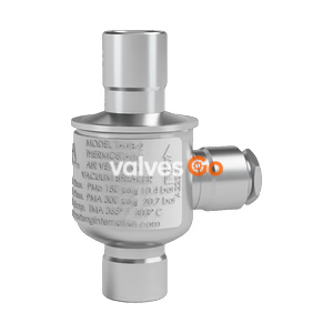
The TLV VC2 is an automatic air vent designed for water piping systems up to 0.5 MPaG and 90 °C. It vents air at start-up and during operation, and can act as a vacuum breaker.
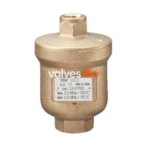
TLV VC2 automatic air vent is designed for water piping systems up to 0.5 MPaG (75 psig). This model vents air at start-up and throughout operation for moderate to hot water up to 90 °C. It may also serve as a vacuum breaker in pressurized systems.
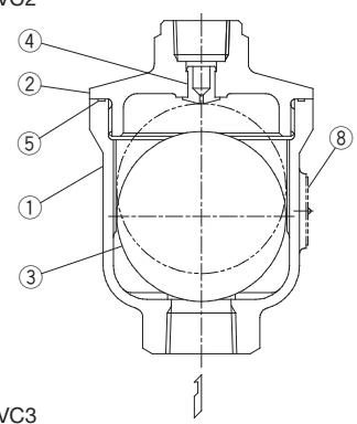
| No. | Part Name |
|---|---|
| 1 | Body |
| 2 | Cover |
| 3 | Float |
| 4 | Valve Seat |
| 5 | Cover Gasket |
| 8 | Name Plate |
| Specification | Value |
|---|---|
| Size Inlet / Outlet | 15 / 10 mm (1/2 / 3/8 in) |
| Maximum Operating Pressure | 0.5 MPaG (75 psig) |
| Minimum Operating Pressure | 0.05 MPaG (7 psig) |
| Maximum Operating Temperature | 90 °C (194 °F) |
| Maximum Allowable Pressure* | 0.5 MPaG (75 psig) |
| Maximum Allowable Temperature* | 185 °C (365 °F) |
WARNING
*Maximum allowable pressure (PMA) and maximum allowable temperature (TMA) are PRESSURE SHELL DESIGN CONDITIONS, NOT OPERATING CONDITIONS.
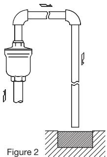
Visual inspections should be carried out periodically to determine whether the automatic air vent is operating properly or has failed. Operational inspections should be performed at least twice per year, or as called for by the air vent operating conditions. Air vent failure may result in damage to piping and equipment, resulting in faulty or low quality product manufacture.
DANGER
NEVER apply direct heat to the float. The float may explode due to increased internal pressure, causing accidents leading to serious injury or property and equipment damage.
Parts Inspection Procedure
| Part | Procedure |
|---|---|
| Gaskets | Check for warping or damage |
| Valve Seat Surface | Check for scratches or wear |
| Float | Check for deformation, damage, oil film or liquid inside |
Disassembly/Reassembly
| Part & No. | Disassembly | Reassembly |
|---|---|---|
| Cover 2 | Clamp the hexagonal part of the vent body in a vice and use a wrench to loosen the cover | Consult the table of tightening torques, coat threads with anti-seize, and tighten to the proper torque |
| Cover Gasket 5 | Remove gasket and clean sealing surfaces | Replace with a new gasket if damaged |
| Valve Seat 4 | Push valve seat inwards from the outlet side, being careful not to scratch. Remove with a socket wrench, being careful not to scratch the seating surface | Using a finger, push into place from the interior side of the cover. Consult the table of tightening torques, coat threads with anti-seize, and tighten to the proper torque |
Tightening Torque and Distance Across Flats
| Part & No. | Torque N·m (lbf·ft) | Distance Across Flats mm (in) |
|---|---|---|
| Cover 2 | 100 (73) | 24 (15/16) |
If the expected performance is unachievable after installation of the air vent, check the following points to take appropriate corrective measures.
| Problem | Cause | Remedy |
|---|---|---|
| No air discharged or discharge is poor (blocked) | Air is not reaching the vent because the liquid in the piping is not being displaced by air | Correct the inlet piping (Inner diameter should be at least 16 mm [5/8"]) |
| Valve seat is clogged | Clean valve seat | |
| Inlet or outlet piping is clogged | Clean piping | |
| The operating pressure exceeds the maximum specified pressure for this product | Replace the air vent with a model that has a suitable operating pressure rating | |
| Water leaks when valve is closed* | Build-up on the surface of the valve seat or the valve seat is damaged. | Clean or replace with new valve seat |
| Float is dirty, coated with a film, or is deformed | Clean or replace with new float | |
| Improper installation | Correct the installation | |
| Valve does not close, and liquid spurts out | Water is inside the float | Replace with new float |
| Specific gravity of the liquid is not suitable for this product (This product is for water systems) | Select a product with suitable specifications for the operating conditions (consult TLV) |
*If there is a rapid rise in water level (caused by rapidly opening a shut-off valve, etc.), a small amount of water may leak with discharged air immediately before the vent closes.
Explore similar products in our catalog