PN16

Yoshitake DP-200 series normally closed pilot-operated solenoid valve for water, air, and oil. Features 0-1.0 MPa working pressure and zero leakage.
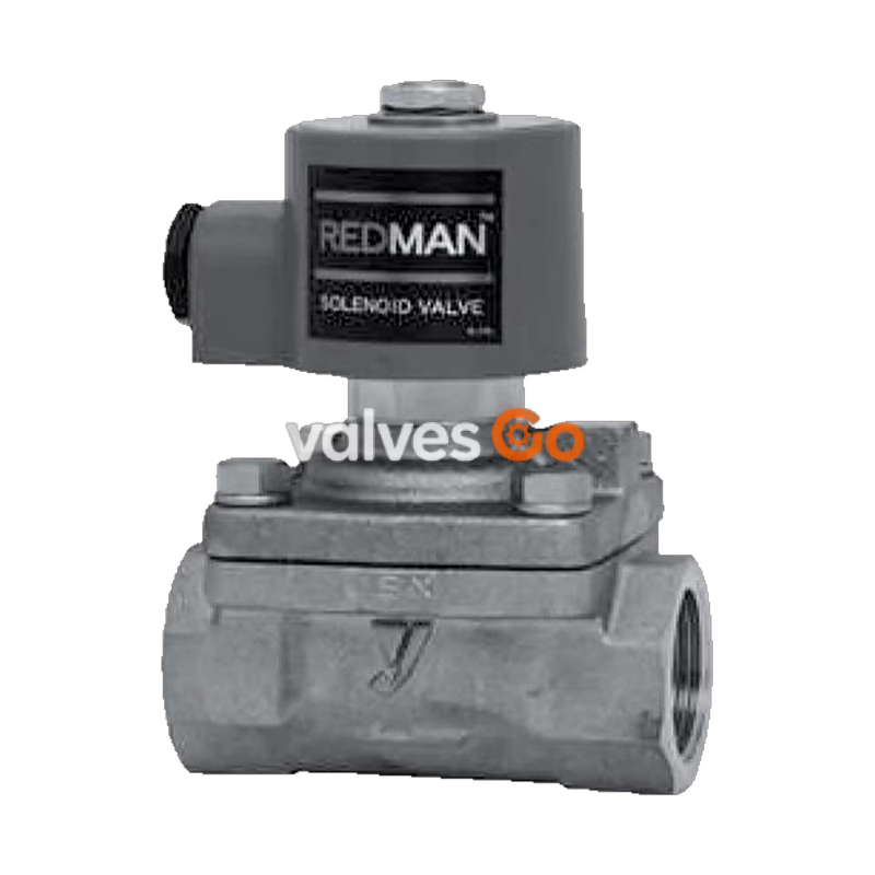
The Yoshitake DP-200 series is a pilot-operated diaphragm solenoid valve designed for automatic on-off control of fluids, including cold and hot water, air, nitrogen gas, carbon dioxide, argon, and oils (up to 20 cSt). It features a cast bronze body and NBR diaphragm, providing a zero-leakage seal for reliable shut-off.
The DP-200 provides a screwed JIS Rc connection, while the DP-200F offers a flanged JIS 10K FF connection. Both are available in normally closed configurations and operate at working pressures from 0 to 1.0 MPa.
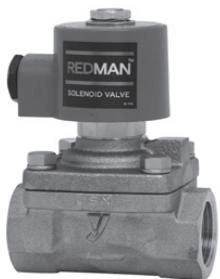
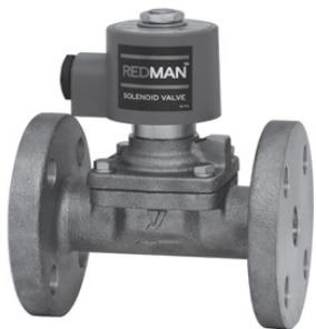
| Model | DP-200, DP-200-N | DP-200F, DP-200F-N |
|---|---|---|
| Normally closed | 10A-50A | 15A-50A |
| Structure | Pilot-operated diaphragm type | Pilot-operated diaphragm type |
| Application | Cold and hot water, Air, N2 gas, CO2 gas (dry), Ar gas, Oil (20 cSt or less) | Cold and hot water, Air, N2 gas, CO2 gas (dry), Ar gas, Oil (20 cSt or less) |
| Working pressure | 0-1.0 MPa (Unusable under vacuum) | 0-1.0 MPa (Unusable under vacuum) |
| Min. differential pressure | 0 MPa (0.1 MPa or more is required if the coil set sideways) | 0 MPa (0.1 MPa or more is required if the coil set sideways) |
| Allowable valve seat leakage | None (by confirming pressure gauge visually) | None (by confirming pressure gauge visually) |
| Temperature range | 5-60°C (no freeze condition) | 5-60°C (no freeze condition) |
| Ambient temperature | 50°C or less (no freeze condition) | 50°C or less (no freeze condition) |
| Installation posture | Vertical or horizontal installation (within 90 degrees from upward position of the coil) | Vertical or horizontal installation (within 90 degrees from upward position of the coil) |
| Body Material | Cast bronze / Bronze (NPb-treated for N models) | Bronze / Bronze (NPb-treated for N models) |
| Diaphragm Material | NBR | NBR |
| Connection | JIS Rc screwed | JIS 10K FF flanged |
INFO
Available with rubber material FKM for the diaphragm. Maximum temperature: 90°C (only for DP-200, DP-200F). Model numbers of the products complying with the Japanese Water Works Law are DP-200-N and DP-200F-N.
| Rated voltage | AC 100 / 200 V or AC 110 / 220 V selective type (50/60 Hz common) |
|---|---|
| Allowable fluctuation | Rated voltage -5% to +10% |
| Insulation class | Insulation class H |
| Protective structure | Dust tight, Splash proof |
| Ingress protection code | IP64 (JIS C0920) |
| Withstand voltage test | 1500 V/min |
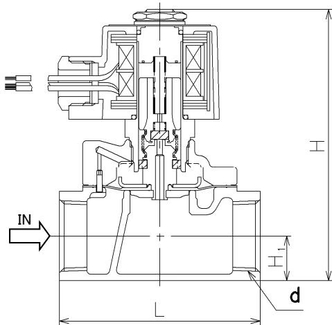
| Nominal size | d | L | H1 | H | Weight (kg) |
|---|---|---|---|---|---|
| 10A | Rc 3/8 | 70 | 14.5 | 114 | 1.1 |
| 15A | Rc 1/2 | 70 | 14.5 | 114 | 1.1 |
| 20A | Rc 3/4 | 80 | 17.5 | 121 | 1.3 |
| 25A | Rc 1 | 95 | 21.0 | 128 | 1.7 |
| 32A | Rc 1-1/4 | 110 | 26.0 | 150 | 2.5 |
| 40A | Rc 1-1/2 | 120 | 29.5 | 157 | 3.1 |
| 50A | Rc 2 | 140 | 36.5 | 172 | 5.0 |
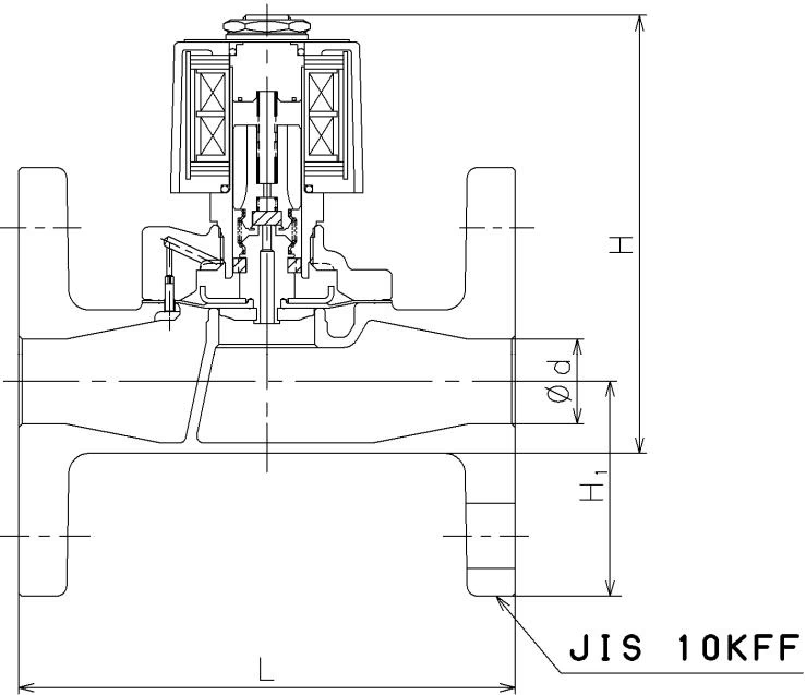
| Nominal size | d | L | H1 | H | Weight (kg) |
|---|---|---|---|---|---|
| 15A | 15 | 120 | 47.5 | 147 | 2.7 |
| 20A | 20 | 130 | 50.0 | 153 | 3.3 |
| 25A | 25 | 145 | 62.5 | 169 | 4.8 |
| 32A | 32 | 160 | 67.5 | 192 | 6.6 |
| 40A | 40 | 170 | 70.0 | 198 | 7.3 |
| 50A | 50 | 195 | 77.5 | 213 | 10.0 |
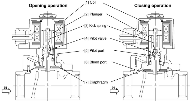
(1) Opening operation (Power ON) When the power is turned ON, the coil is excited and pulls up the plunger, to open the pilot valve. Next, the pressure at the upper part of the diaphragm drops since it flows to the outlet through the pilot port. The diaphragm is then lifted up to the open position by the inlet pressure.
(2) Closing operation (Power OFF) When the power is turned OFF, the coil excitation is canceled and the plunger drops down by force of the kick spring, to close the pilot valve. The pressure at the upper part of the diaphragm rises due to the incoming inlet pressure from the bleed port which is communicated with the inlet. With the support of the kick spring, this makes the diaphragm pushed down to the closed position.
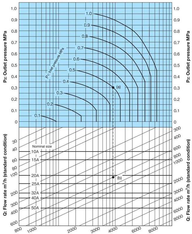
When selecting the nominal size of a solenoid valve whose inlet pressure (P1), outlet pressure (P2), and air (20˚C) flow rate (Q) are 0.5 MPa, 0.3 MPa, and 600 m³/h (standard condition), respectively, first find intersection point (A) of P1 = 0.5 MPa and P2 = 0.3 MPa. Trace down vertically from this intersection point (A) to find intersection point (B) with Q = 600 m³/h (standard condition). Since this intersection point (B) lies between nominal sizes 20A and 25A, select the larger one, 25A.
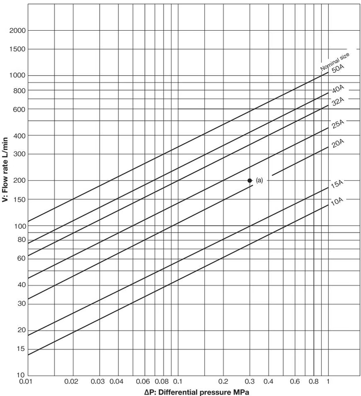
When selecting the nominal size of a solenoid valve whose inlet pressure (P1), outlet pressure (P2), and flow rate (V) are 0.6 MPa, 0.3 MPa, and 200 L/min, respectively, first find intersection point (A) of the differential pressure before and after the valve [∆P = 0.6 – 0.3 = 0.3 MPa] and V = 200 L/min. Since this intersection point (A) lies between nominal sizes 20A and 25A, select the larger one, 25A.
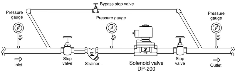
WARNING
Yoshitake Actuation & Positioners / Solenoid
DD and DP series solenoid valves for automatic fluid shutoff and interlocking control.
Explore similar products in our catalog