Stainless Steel

Yoshitake ES-10-200 sleeve type expansion joint for steam, air, water, and oil. Features 1.0 MPa max pressure, 220°C max temperature, and hard chrome plated sleeve.
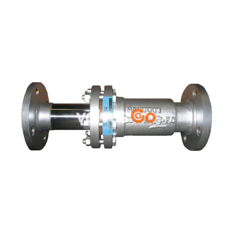
Yoshitake ES-10-200 is a sleeve type expansion joint designed for steam, air, cold and hot water, oil, and other non-dangerous fluids. It complies with SHASE-S003 standards and features a large expansion and compression length, which significantly reduces the need for multiple pipe joints and anchors in the piping system. The sleeve surface is hard chrome plated, providing outstanding corrosion and wear resistance for long-term reliability.
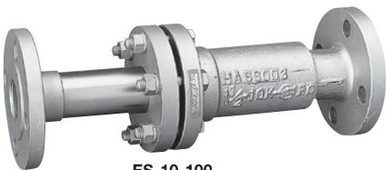
| Model | ES-10-200 | ES-11-200 |
|---|---|---|
| Application | Steam, Air, Cold and hot water, Oil, Other non-dangerous fluids | Steam, Air, Cold and hot water, Oil, Other non-dangerous fluids |
| Maximum pressure | 1.0 MPa | 2.0 MPa |
| Maximum temperature | 220°C | 220°C |
| Max. axial extension | 40 mm | 40 mm |
| Max. axial compression | 160 mm | 160 mm |
| Material (Body) | Ductile cast iron or Rolled steel * | Ductile cast iron or Rolled steel * |
| Material (Sleeve) | Carbon steel (HCr plating) | Carbon steel (HCr plating) |
| Connection | JIS 10K RF flanged | JIS 20K RF flanged |
Note: Ductile cast iron for 25A to 100A. Rolled steel for 125A to 200A.
Precautions before installation
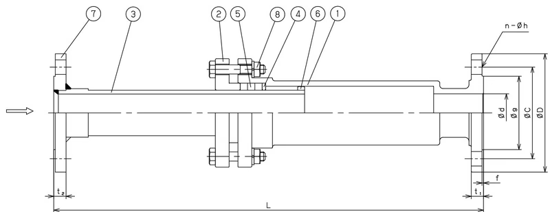
| Nominal size | Set length L (mm) | Max. operating length (mm) | Min. operating length (mm) | Max. axial extension δ (mm) | Do (mm) | Nominal size of bolt thread | Quantity |
|---|---|---|---|---|---|---|---|
| 25A | 560 | 600 | 400 | 200 | 114 (125) | M12 x 60 | 4 |
| 32A | 560 | 600 | 400 | 200 | 124 (135) | M12 x 65 | 4 |
| 40A | 560 | 600 | 400 | 200 | 130 (140) | M12 x 65 | 6 |
| 50A | 560 | 600 | 400 | 200 | 142 (155) | M12 x 65 | 6 |
| 65A | 600 | 640 | 440 | 200 | 175 (175) | M16 x 75 | 6 |
| 80A | 600 | 640 | 440 | 200 | 188 (200) | M16 x 75 | 6 |
| 100A | 640 | 680 | 480 | 200 | 216 (225) | M16 x 80 | 8 |
| 125A | 640 | 680 | 480 | 200 | 242 (270) | M16 x 80 | 10 |
| 150A | 690 | 730 | 530 | 200 | 290 (305) | M20 x 90 | 10 |
| 200A | 690 | 730 | 530 | 200 | 340 (350) | M20 x 90 | 12 |
Note: The value in () is the dimension of ES-11-200.
Secure anchors and guides are required to make full use of the function of the joint connected to piping. The piping system shall be equipped with main anchors at the following positions:
Mount a main anchor at both ends of the piping, each branch point, and the location where a reducer or valve is installed. These main anchors need to be strong enough to withstand the force required to stretch or contract the sleeve plus the internal pressure thrust resulting from the effect of the internal fluid pressure.
F_MA = F_S + F_M + F_G
Where:
Table 1: Load acting on the main anchor of straight pipe
| Nominal size | 25A | 32A | 40A | 50A | 65A | 80A | 100A | 125A | 150A | 200A |
|---|---|---|---|---|---|---|---|---|---|---|
| Effective area a (cm²) | 9.1 | 13.9 | 18.1 | 28.3 | 45.6 | 62.2 | 102.0 | 151.7 | 213.7 | 366.0 |
| F_S at 0.2MPa (N) | 182 | 278 | 362 | 566 | 906 | 1244 | 2040 | 3034 | 4174 | 7320 |
| F_S at 0.4MPa (N) | 364 | 556 | 724 | 1132 | 1812 | 2488 | 4080 | 6068 | 8548 | 14640 |
| F_S at 0.6MPa (N) | 546 | 834 | 1086 | 1698 | 2718 | 3732 | 6120 | 9102 | 12822 | 21960 |
| F_S at 0.8MPa (N) | 728 | 1112 | 1448 | 2264 | 3624 | 4976 | 8160 | 12136 | 17096 | 29280 |
| F_S at 1.0MPa (N) | 910 | 1390 | 1810 | 2830 | 4530 | 6220 | 10200 | 15170 | 21370 | 36600 |
| Frictional force F_M (N) | 2300 | 2500 | 3300 | 4000 | 5100 | 6200 | 7520 | 9400 | 11300 | 14800 |
In case of vertical piping, the piping mass and fluid mass are further loaded, so when calculating the anchor strength, add them together. Make sure to install the product with no misalignment of the piping. Misalignment may lead to noise or damage from the sleeve.
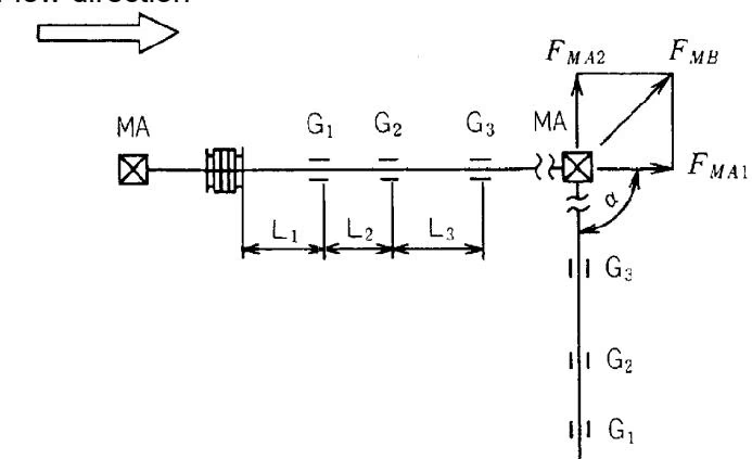
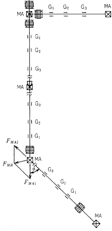
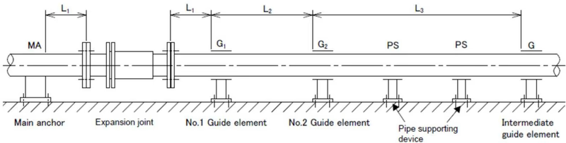
In a piping using expansion joints for absorbing axial movements, guide elements (G) shall be installed to align the pipe joint and pipe and transmit the force necessary for axial movement smoothly to the anchor.
Keep the misalignment of 125A and smaller piping within ±2 mm and that of 150A and larger piping within ±3 mm. Adjust the parallelism of piping to ±0.5° or less.
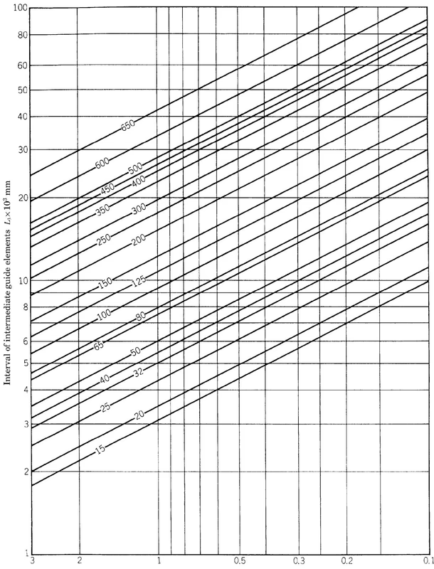
The thermal expansion or contraction length of piping (Δℓ) shall be obtained according to the formula: Δℓ = β(T - t1)ℓ
Where:
Table 2: Linear expansion coefficient of piping (×10⁻⁶/°C)
| Temperature (°C) | Carbon steel, Low chrome steel | Austenitic stainless steel |
|---|---|---|
| 0 | 10.75 | 16.27 |
| 100 | 11.53 | 16.84 |
| 200 | 12.24 | 17.25 |
| 220 | 12.38 | 17.32 |
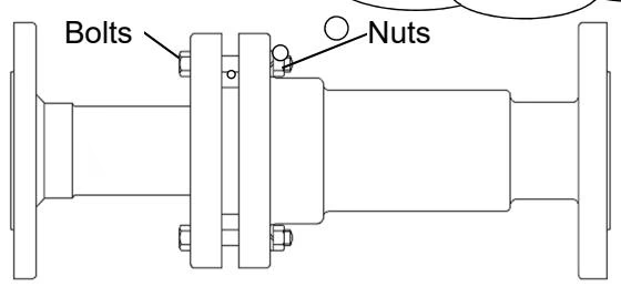
Warning
Yoshitake Piping Accessories
BJ, ES, MS, and YS series piping accessories for connection, expansion, and installation in fluid systems.
Explore similar products in our catalog