


PN25

Yoshitake GD-200 series ductile cast iron pressure reducing valve for cold and hot water, oil, and air. Features a pressure balance structure, 10:1 max reduction ratio, and JIS flanged connection.
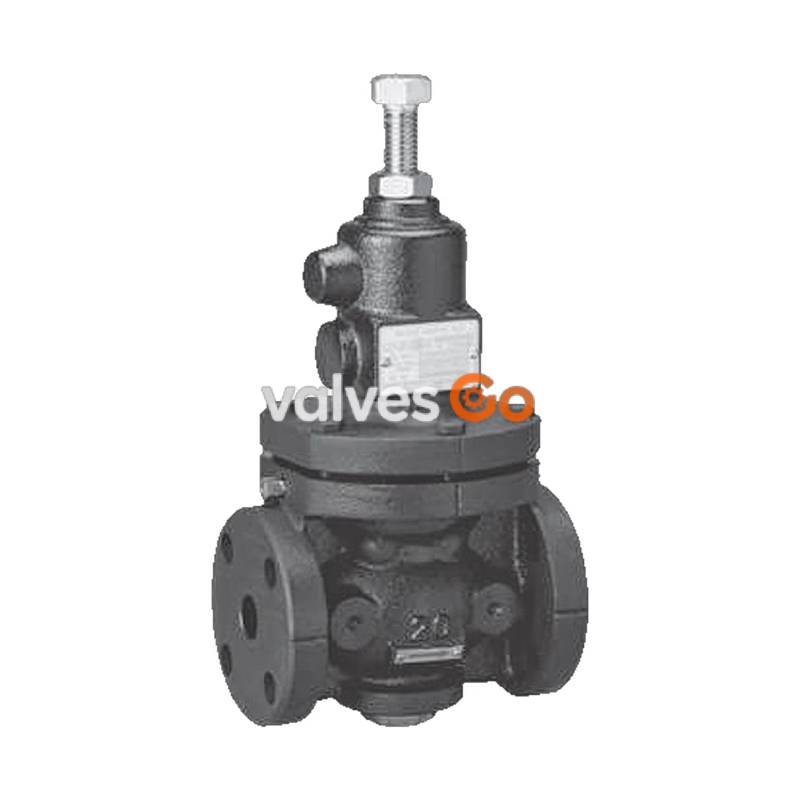
Yoshitake GD-200 series pressure reducing valves are designed for cold and hot water, oil (kerosene, heavy oils A and B), air, and other non-dangerous fluids. These ductile cast iron valves utilize a pressure balance structure to maintain reduced pressure at a constant level, unaffected by inlet pressure fluctuations. The series includes the standard GD-200, the GD-200H for higher inlet pressures (up to 2.0 MPa), and the GD-200C-N with a Nylon 11 coated body for excellent corrosion resistance.
| Model | GD-200 | GD-200C-N | GD-200H |
|---|---|---|---|
| Application | Cold and hot water, Oil, Air, Other non-dangerous fluids | Cold and hot water | Cold and hot water, Oil, Air, Other non-dangerous fluids |
| Inlet Pressure | 1.0 MPa or less | 1.0 MPa or less | 2.0 MPa or less |
| Minimum Differential Pressure | 0.05 MPa | 0.05 MPa | 0.05 MPa |
| Maximum Pressure Reduction Ratio | 10:1 | 10:1 | 10:1 |
| Application Temperature | 5-80°C | 5-60°C | 5-80°C |
| Body Material | Ductile cast iron | Ductile cast iron | Ductile cast iron |
| Valve Seat Material | Stainless steel | Stainless steel | Stainless steel |
| Valve Disc / Diaphragm | NBR | EPDM or FKM | NBR |
| Connection | JIS 10K FF flanged | JIS 10K FF flanged | JIS 20K RF flanged |
Options
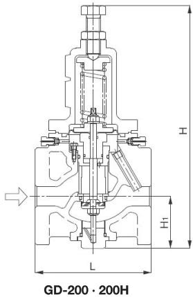
| Nominal Size | L | H (GD-200) | H (GD-200H) | H1 | Weight (kg) GD-200 | Weight (kg) GD-200H |
|---|---|---|---|---|---|---|
| 15A | 145 | 310 | 310 | 57 | 8.2 | 8.2 |
| 20A | 150 | 310 | 310 | 57 | 8.2 | 8.2 |
| 25A | 150 | 333 | 333 | 67 | 10.0 | 10.0 |
| 32A | 195 | 397 | 397 | 76 | 17.3 | 17.3 |
| 40A | 195 | 397 | 397 | 76 | 17.3 | 17.3 |
| 50A | 195 | 415 | 415 | 81 | 19.2 | 19.2 |
| 65A | 270 | 555 | 555 | 110 | 40.0 | 40.0 |
| 80A | 270 | 582 | 582 | 125 | 43.7 | 43.7 |
| 100A | 308 | 645 | 645 | 143 | 70.0 | 70.7 |
| 125A | 380 | 849 | 849 | 179 | 144.0 | 145.0 |
| 150A | 400 | 918 | 918 | 204 | 173.0 | 175.0 |
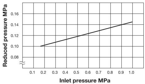 This chart shows variation in reduced pressure when the inlet pressure of 1.0 MPa is changed between 0.15 MPa and 1.0 MPa while the reduced pressure is set at 0.10 MPa.
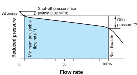
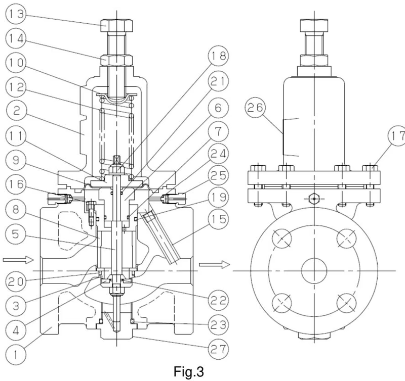 If the adjusting screw is turned right, the diaphragm will be depressed with the spring and the valve disc connected with the spindle will open. Load to the diaphragm balances with the load of the spring, adjusting the opening of the main valve to regulate the reducing pressure.
Installation Cautions
Yoshitake Control Valves / Pressure Reducing Valves
GP, GD, and CP series for stable pressure reduction and control in steam, water, and air systems.
Explore similar products in our catalog



