Feed-Forward Design

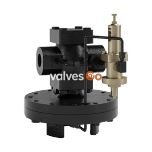
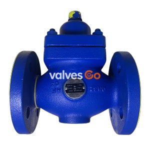
Yoshitake GD-20R and GD-20RC primary pressure regulating and pressure sustaining valves. Features single seat design, large diaphragm, and robust corrosion resistance for water, oil, and air applications.
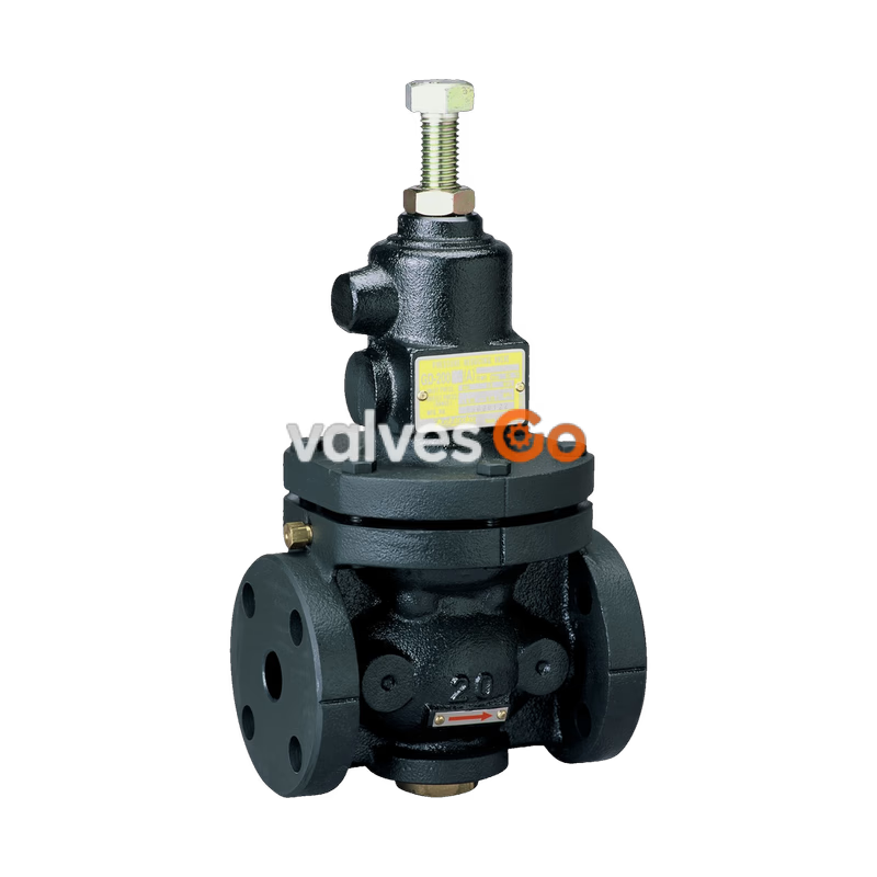
Yoshitake GD-20R and GD-20RC are primary pressure regulating valves and pressure sustaining valves designed for water, oil, air, and other non-dangerous fluids. These valves relieve excess pressure caused by load fluctuations and keep the internal pressure of piping constant during pump operation. They are also widely used to sustain water pressure inside piping when the pump of an open circuit system for mid-rise or high-rise building equipment is shut down.
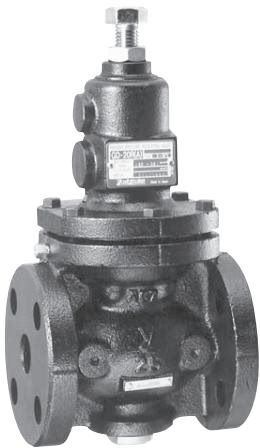
| Model | GD-20R | GD-20RC |
|---|---|---|
| Application | Cold and hot water, Oil (kerosene, heavy oils A and B), Air, Other non-dangerous fluids | Cold and hot water, Oil (kerosene, heavy oils A and B), Air, Other non-dangerous fluids |
| Pressure Regulating Range | 15A–80A: (A) 0.05–0.25 MPa, (B) 0.26–0.7 MPa 100A–150A: (A) 0.05–0.25 MPa, (B) 0.26–0.5 MPa | 15A–80A: (A) 0.05–0.25 MPa, (B) 0.26–0.7 MPa 100A–150A: (A) 0.05–0.25 MPa, (B) 0.26–0.5 MPa |
| Fluid Temperature | 5–80°C | 5–60°C |
| Fluid Viscosity | 600 cSt or less | 600 cSt or less |
| Body Material | Ductile cast iron | Ductile cast iron |
| Valve Seat | Stainless steel or Bronze | Stainless steel or Bronze |
| Valve Disc & Diaphragm | NBR | NBR |
| Connection | JIS 10K FF flanged | JIS 10K FF flanged |
| Inside Surface Treatment | 15A–100A: Electrodeposition coating 125A–150A: Tar-based coating (Black) or Electrodeposition coating | Nylon 11 (inside and outside surfaces) |
INFO
| Nominal Size | L (mm) | H (mm) | H1 (mm) | Weight (kg) |
|---|---|---|---|---|
| 15A | 145 | 309 | 57 | 8.2 |
| 20A | 150 | 309 | 57 | 8.2 |
| 25A | 150 | 330 | 67 | 10.0 |
| 32A | 195 | 395 | 76 | 17.3 |
| 40A | 195 | 395 | 76 | 17.3 |
| 50A | 195 | 409 | 81 | 19.2 |
| 65A | 270 | 555 | 105 | 40.0 |
| 80A | 270 | 582 | 120 | 43.7 |
| 100A | 308 | 645 | 135 | 70.0 |
| 125A | 380 | 849 | 169 | 144.0 |
| 150A | 400 | 918 | 204 | 173.0 |
Weights are for GD-20R.
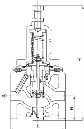 The material shapes are slightly different depending on the nominal size.
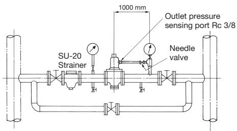 Install a needle valve to the outlet side of the product and plumb it to the pressure sensing pipe using copper piping.
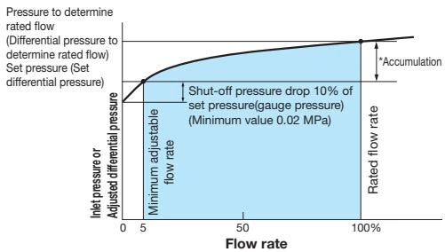
| Set Range (MPa) | Accumulation (MPa) |
|---|---|
| 0.05–0.25 | Within 0.05 |
| 0.26–0.7 | Within 0.105 |
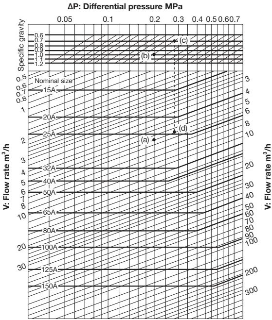
When selecting the nominal size of a differential pressure regulating valve whose differential pressure (ΔP), specific gravity, and flow rate (V) are 0.2 MPa, 1 (water), and 5.5 m³/h, respectively, first trace down vertically from the differential pressure (ΔP) of 0.2 MPa to find intersection point (a) with the flow rate (V) of 5.5 m³/h. Since this intersection point (a) lies between nominal sizes 25A and 32A, select the larger one, 32A.
When the specific gravity is 0.7 under the same conditions, trace down vertically from the differential pressure (ΔP) of 0.2 MPa to find intersection point (b) with the specific gravity 1. Find intersection point (c) with the specific gravity of 0.7 by tracing horizontally to the slant lines from this intersection point (b). Then, find intersection point (d) with the flow rate (V) of 5.5 m³/h by tracing down vertically from intersection point (c). Since this intersection point (d) lies between nominal sizes 20A and 25A, select the larger one, 25A.
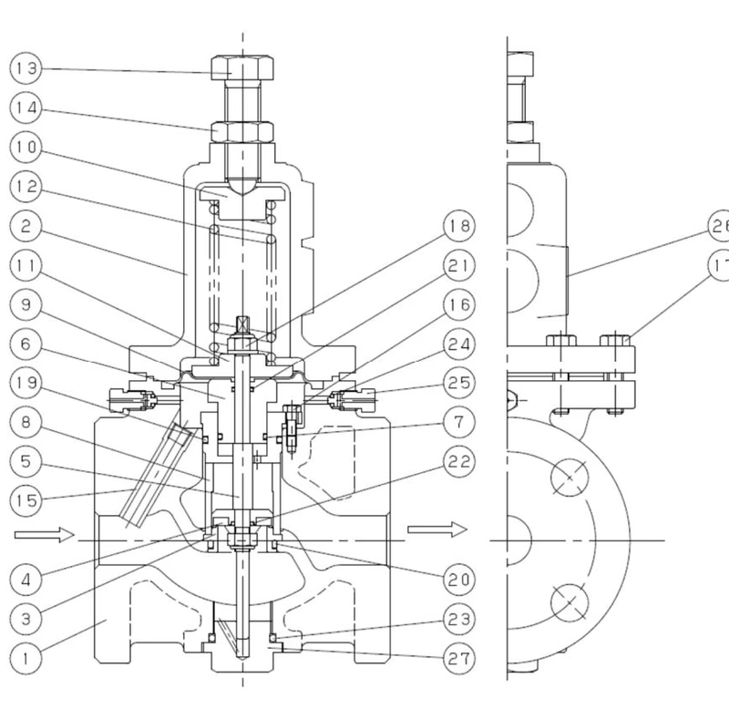
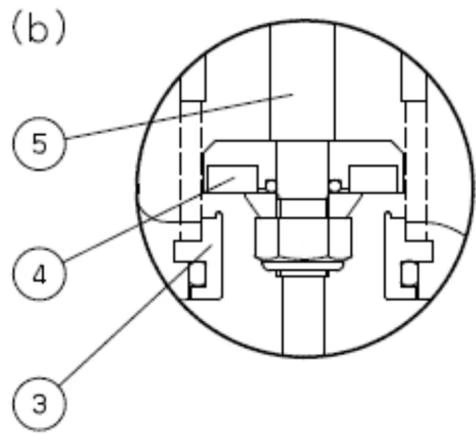
If the adjusting screw is turned right, the diaphragm will be depressed with the adjusting spring and the valve connected with the spindle will close.
Fluid passes along a conductor pipe and the sensing chamber under the diaphragm. If the pressure of the sensing chamber becomes higher than the setting pressure, the load of the diaphragm bottom will overcome the load of the adjusting spring, will push up the valve, and will relieve excessive pressure.
If the pressure of the sensing chamber falls below the setting pressure, the valve will be again closed by the load of the adjusting spring.
Yoshitake Control Valves / Self-operated Regulators
OB, GPR, CF, and GD series self-operated regulators for pressure and temperature control without external power.
Explore similar products in our catalog