


PN25

Yoshitake GD-41 direct type pressure reducing valve features a space-saving cast stainless steel body. Ideal for cold and hot water, air, gases, and sterilization steam. Maintains constant reduced pressure.
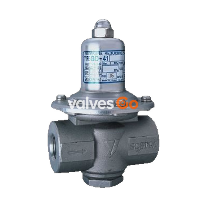
Yoshitake GD-41 series is a highly durable direct type pressure reducing valve designed for space saving and excellent corrosion resistance. The wetted parts are made of cast stainless steel (SCS14A and SUS316), and the diaphragm contact surface is completely covered with PTFE, making it highly durable and suitable for a wide range of fluids including cold and hot water, air, carbon dioxide gas, nitrogen gas, and sterilization steam.
Thanks to its built-in pressure balance structure, the valve keeps the reduced pressure constant without being affected by fluctuations in the inlet pressure. The closed structure prevents fluid from flowing to the outside, providing a high level of safety and reliability for various industrial applications. Selected models in the family, such as the GD-41N and GD-43N, are approved by the JWWA (Japan Water Works Association).
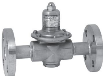
| Model | GD-41 | GD-43-10 | GD-43-20 | GD-41N | GD-43N-10 | GD-43N-20 |
|---|---|---|---|---|---|---|
| Application | Cold and hot water / Steam for washing or sterilization | |||||
| Inlet pressure | 0.07-2.0 MPa (0.2 MPa or less for steam for washing or sterilization) * | |||||
| Reduced pressure | (A) Yellow spring: 0.02-0.1 MPa (B) Red spring: 0.1-0.25 MPa (C) Black spring: 0.25-0.5 MPa | |||||
| Minimum differential pressure | 0.05 MPa | |||||
| Maximum pressure reduction ratio | Cold and hot water: 10:1 | |||||
| Fluid temperature | 5-90°C (Max temperature of steam for washing or sterilization is 130°C) | |||||
| Body Material | Cast Stainless steel (SCS14A) | |||||
| Valve disc Material | Special synthetic rubber (special FKM) | |||||
| Diaphragm Material | Heat-resistant synthetic rubber and PTFE | |||||
| Connection | JIS Rc screwed | JIS 10K FF flanged | JIS 20K RF flanged | JIS Rc screwed | JIS 10K FF flanged | JIS 20K RF flanged |
Precautions for Steam
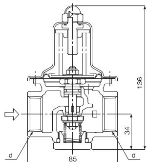
| Nominal size | d | Weight (kg) |
|---|---|---|
| 15A | Rc 1/2 | 1.2 |
| 20A | Rc 3/4 | 1.1 |
| 25A | Rc 1 | 1.0 |
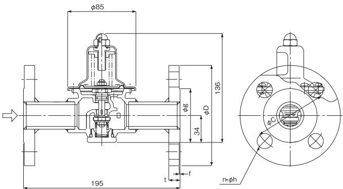
| Size | D | C | g | t | f | n-h | Weight (kg) |
|---|---|---|---|---|---|---|---|
| 15A | 95 | 70 | 51 | 14 (12) | 1 | 4-15 | 2.8 (2.6) |
| 20A | 100 | 75 | 56 | 16 (14) | 1 | 4-15 | 3.0 (2.9) |
| 25A | 125 | 90 | 67 | 16 (14) | 1 | 4-19 | 4.0 (3.7) |
Note: The values in parentheses are the dimensions/weights of the GD-43-10 and GD-43N-10.
Flow Characteristic Chart
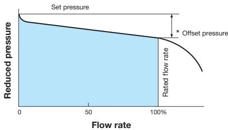
| Set pressure | Offset pressure |
|---|---|
| 0.2 MPa or less | Within 0.05 MPa |
| More than 0.2 MPa | Within 0.08 MPa |
Pressure Characteristic Chart
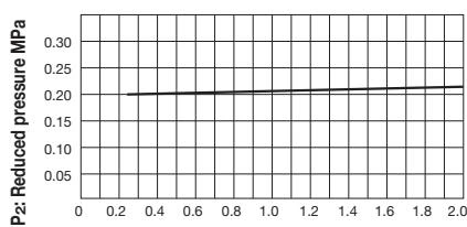
This chart shows the variation in reduced pressure when the inlet pressure of 0.25 MPa is changed up to 2.0 MPa while the reduced pressure is firmly set at 0.20 MPa.
General Safety Warning
When installing a safety valve at the outlet side of the pressure reducing valve, always connect a blow-off pipe to the outlet of the safety valve to lead the possible discharged fluid to a safe location.
Installation Precautions
Maintenance and Component Replacement
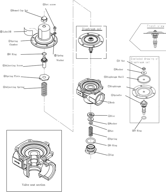
To maintain optimal functions and performance of the pressure reducing valve, perform periodic checks and replace expendable parts based on usage frequency.
Standard Replacement Intervals:
Yoshitake Control Valves / Pressure Reducing Valves
GP, GD, and CP series for stable pressure reduction and control in steam, water, and air systems.
Explore similar products in our catalog



