


PN25

Yoshitake GD-6 direct-acting diaphragm pressure reducing valve for water, oil, and air. Features 0.1-1.0 MPa inlet pressure and highly accurate controllability.
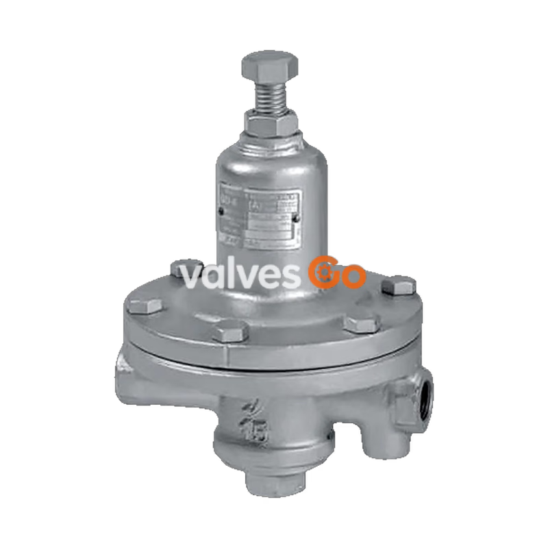
Yoshitake GD-6 is a direct-acting diaphragm pressure reducing valve designed for cold and hot water, oil, air, and other non-dangerous fluids. It features highly accurate controllability of reduced pressure even at small flow rates.
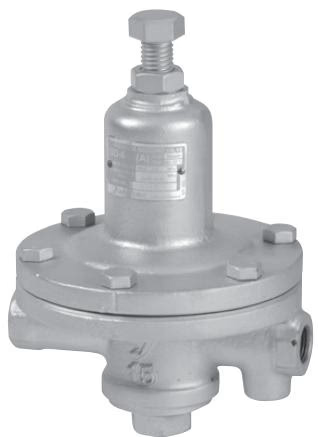
| Model | GD-6 |
|---|---|
| Application | Cold and hot water, Oil, Air, Other non-dangerous fluids |
| Inlet pressure | 0.1-1.0 MPa |
| Reduced pressure | (A) 0.02-0.1 MPa (Nameplate color: yellow) (B) 0.1-0.4 MPa (Nameplate color: blue) |
| Minimum differential pressure | 0.05 MPa |
| Maximum pressure reduction ratio | 10:1 |
| Application temperature | 5-80℃ |
| Valve seat leakage | None |
| Fluid viscosity | 300 cSt or less |
| Body Material | Ductile cast iron *1 |
| Valve, valve seat Material | Brass and bronze (FKM disc incorporated) *2 |
| Diaphragm Material | Stainless steel |
| Connection | JIS Rc screwed |
*1 Available with stainless steel wetted parts and all stainless steel made on request. *2 Available with stainless steel made valve disc and valve seat on request. Also available with PTFE disc on request. Available with anticorrosive (fluororesin-coated) type on request.
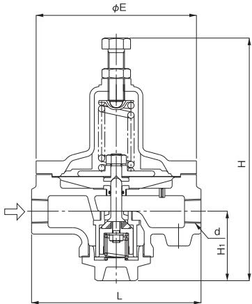
| Nominal size | d | L | H | H1 | E | Weight (kg) |
|---|---|---|---|---|---|---|
| 10A | Rc 3/8 | 165 | 243 | 57 | 155 | 5.5 |
| 15A | Rc 1/2 | 165 | 243 | 57 | 155 | 5.5 |
| 20A | Rc 3/4 | 185 | 267 | 76 | 175 | 8.2 |
| 25A | Rc 1 | 185 | 267 | 76 | 175 | 8.2 |
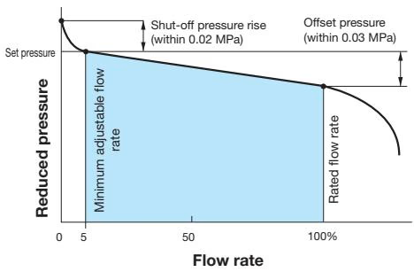
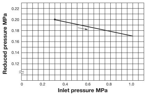
This chart shows variation in reduced pressure when the inlet pressure of 0.3 MPa is changed between 0.3 MPa and 1.0 MPa while the reduced pressure is set at 0.2 MPa.
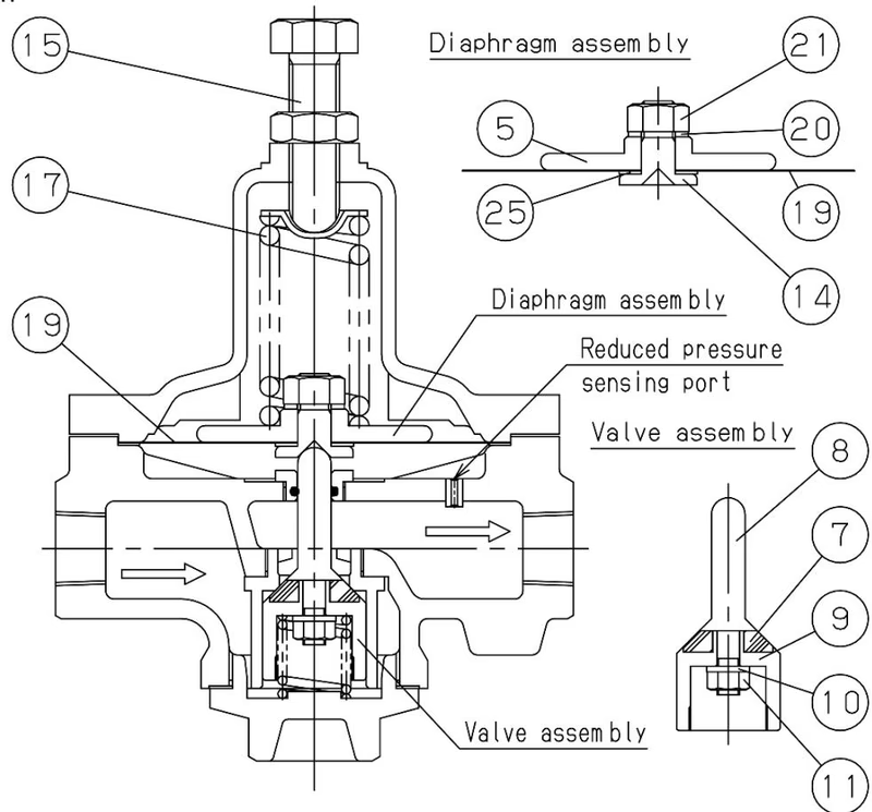
When the adjusting screw [15] is screwed in, the adjusting spring [17] is compressed, which lowers the diaphragm [19] and opens the valve assembly to allow the fluid to flow to the secondary side. When the secondary side pressure increases or decreases, the diaphragm [19] and adjustment spring [17] balance, adjust the valve opening, and maintain the secondary side pressure constant.
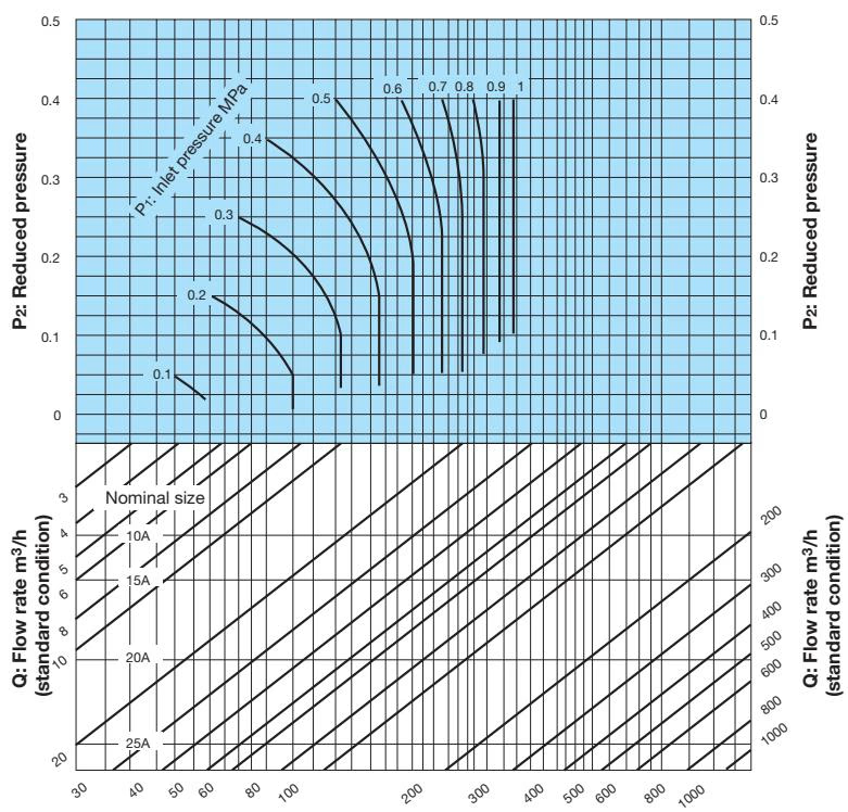
For Air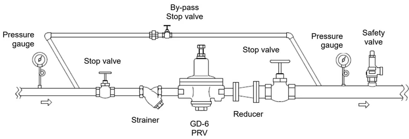
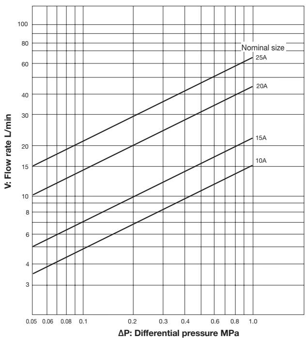
For Water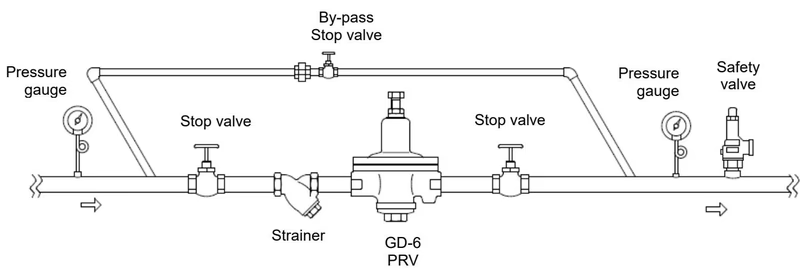
Precautions Before Operation
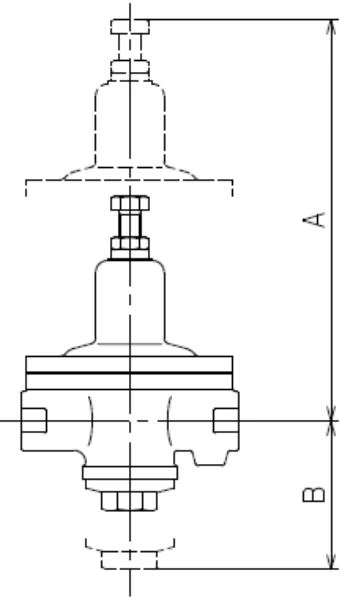
Maintenance Space
In order to have easy maintenance, be sure to have enough space for inspection.
Warning
Do not touch the valve directly with bare hands. Doing so may result in burns.
| Problem | Causes | Solutions |
|---|---|---|
| Pressure does not rise to desired level. | 1. Incorrect pressure is being used. 2. Nominal size is too small. 3. Incorrect adjustment. 4. Strainer is clogged. 5. Pressure gauge malfunction. 6. Reduced pressure sensing port is clogged. | 1. Correct the pressure. 2. Replace with the correct size. 3. Re-adjust. 4. Disassemble and clean. 5. Replace the pressure gauge. 6. Disassemble and clean. |
| Reduced pressure exceeds prescribed level. | 1. Foreign matter is embedded in valve/seat, or scratches exist. 2. By-pass valve is leaking. | 1. Disassemble and clean. If scratches exist, replace them. 2. Repair or replace the valve. |
| External leakage | 1. Diaphragm is broken. 2. Gasket is broken. | 1. Replace the diaphragm. 2. Replace the gasket. |
| Abnormal noise is heard. | 1. Nominal size is too large. 2. Pressure reduction ratio is too large. 3. Air problem is caused (Liquid use). 4. An abrupt OPEN/CLOSE valve is too close. | 1. Replace with correct size. 2. Use a two-stage reduction. 3. Install an air trap. 4. Keep distance at least 3m. |
Consumables Replacement
Yoshitake Control Valves / Pressure Reducing Valves
GP, GD, and CP series for stable pressure reduction and control in steam, water, and air systems.
Explore similar products in our catalog



