


PN25

Yoshitake GP-1000EN pressure reducing valve for steam. Features ductile cast iron body, stainless steel trim, and EN PN16 RF flanged connection. Max inlet pressure 1.0 MPa, max temperature 220°C.
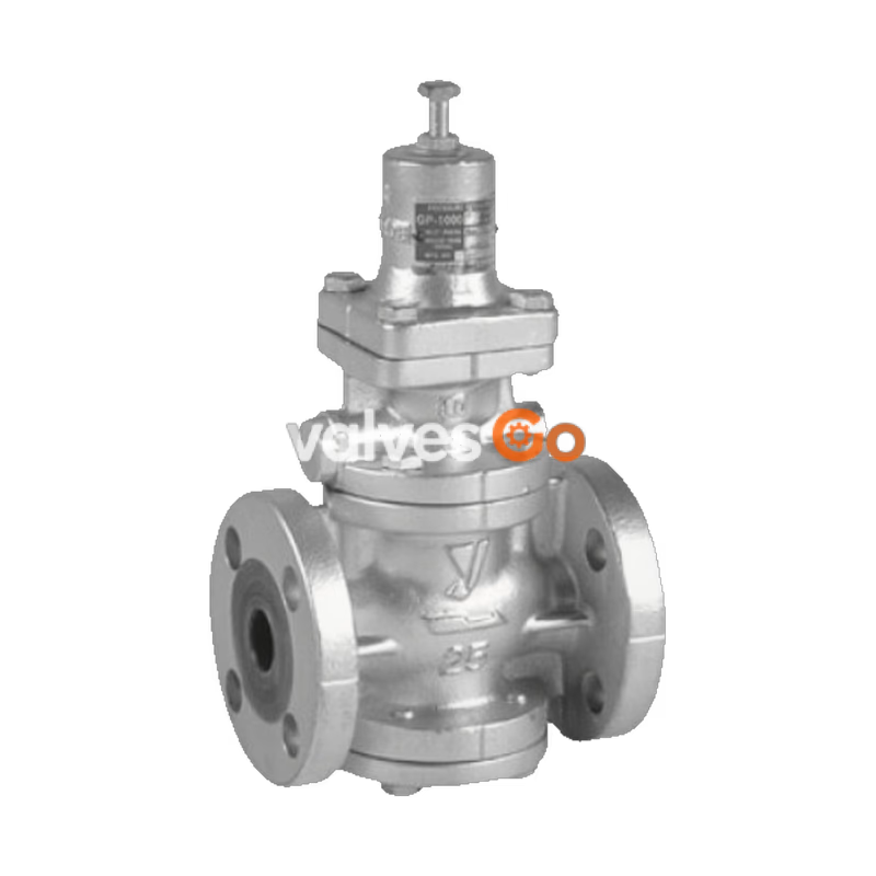
The Yoshitake GP-1000EN is a high-performance pressure reducing valve designed for steam applications. It features a ductile cast iron body and stainless steel trim, equipped with an EN PN16 RF flanged connection. The spherical main valve offers excellent sealability, greatly reducing valve seat leakage to comply with ANSI Class IV standards.
| Specification | Value |
|---|---|
| Application | Steam |
| Inlet pressure | 0.1 - 1.0 MPa |
| Reduced pressure | 0.05 - 0.9 MPa (90% or less of inlet pressure) |
| Minimum differential pressure | 0.05 MPa |
| Maximum pressure reduction ratio | 20:1 |
| Maximum temperature | 220°C |
| Valve seat leakage | 0.01% or less of rated flow |
| Body Material | Ductile cast iron |
| Valve, valve seat Material | Stainless steel |
| Piston, Cylinder Material | Brass or bronze |
| Connection | EN PN16 RF flanged |
INFO
Available with trim parts (piston and cylinder) made of stainless steel (GP-1000ENS).
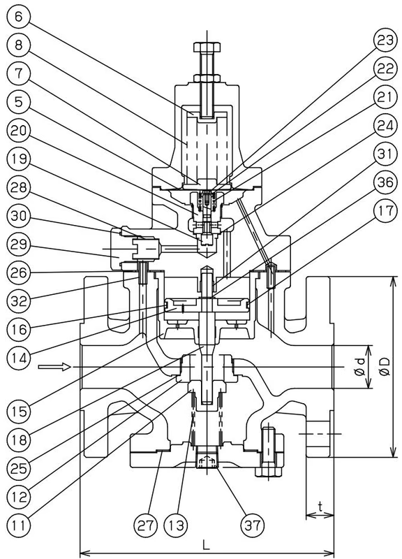
| Size | L (mm) | H1 (mm) | H (mm) | Flange D (mm) | Flange C (mm) | Flange t (mm) | n-h | Weight (kg) |
|---|---|---|---|---|---|---|---|---|
| 15A | 150 | 64 | 291 | 95 | 65 | 16 | 4-14 | 8.0 |
| 20A | 150 | 64 | 291 | 105 | 75 | 16 | 4-14 | 8.5 |
| 25A | 160 | 67 | 300 | 125 | 85 | 18 | 4-14 | 10.0 |
| 32A | 180 | 82 | 333 | 140 | 100 | 20 | 4-19 | 14.0 |
| 40A | 200 | 82 | 333 | 150 | 110 | 20 | 4-19 | 15.5 |
| 50A | 230 | 93 | 353 | 165 | 125 | 20 | 4-19 | 21.0 |
| 65A | 290 | 100 | 357 | 185 | 145 | 21 | 4-19 | 30.0 |
| 80A | 310 | 122 | 404 | 210 | 160 | 28 | 8-19 | 37.0 |
| 100A | 350 | 144 | 450 | 254 | 180 | 32 | 8-19 | 57.0 |
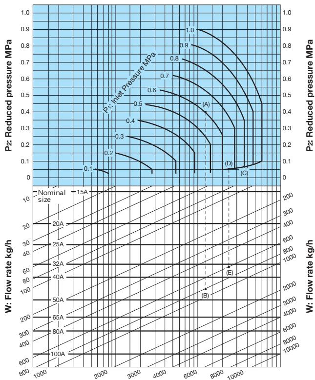
[Example 1] When selecting the nominal size of a pressure reducing valve whose inlet pressure (P1), reduced pressure (P2), and steam flow rate are 0.6 MPa, 0.4 MPa, and 800 kg/h, respectively, first find intersection point (A) of the inlet pressure of 0.6 MPa and the reduced pressure of 0.4 MPa. Trace down vertically from this intersection point to find intersection point (B) with the flow rate of 800 kg/h. Since intersection point (B) lies between nominal sizes 40A and 50A, select the larger one, 50A.
[Example 2] When selecting the nominal size of a pressure reducing valve whose inlet pressure (P1), reduced pressure (P2), and steam flow rate are 0.8 MPa, 0.05 MPa, and 600 kg/h, respectively, first find intersection point (C) of the inlet pressure of 0.8 MPa and the diagonal line. Trace down to the left from this intersection point to find intersection point (D) with the reduced pressure of 0.05 MPa. Trace down vertically from intersection point (D) to find intersection point (E) with the flow rate of 600 kg/h. Since intersection point (E) lies between nominal sizes 32A and 40A, select the larger one, 40A.
TIP
Set the safety factor at 80 to 90%.
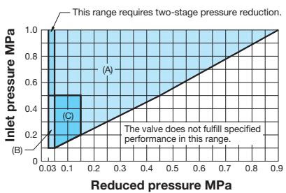 Find the intersection point of the inlet and reduced pressures. If the intersection point is within any of the ranges shown in the chart above, the pressures are controllable. (Range A and C cover GP-1000 Series).
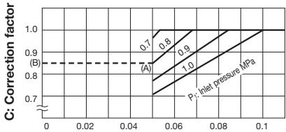 Example: Take a pressure reducing valve whose inlet pressure is 0.8 MPa, the reduced pressure is 0.05 MPa. Find the inlet and reduced pressure intersection point (A) at the above chart, then draw a horizontal line in the leftward direction to point (B) which indicates a correction coefficient of 0.85. For a nominal size of 25A, the corrected Cv value would be calculated as follows (based on formula in source).
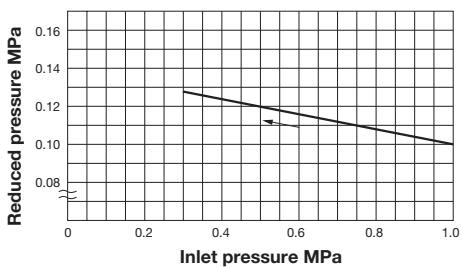 This chart shows variation in reduced pressure when the inlet pressure of 1.0 MPa is changed between 0.3 MPa and 1.0 MPa while the reduced pressure is set at 0.1 MPa.
Set pressure of safety valve for alarm use at the outlet side of the pressure reducing valve for steam:
| Set pressure of pressure reducing valve (MPa) | Set pressure of safety valve (MPa) |
|---|---|
| 0.1 or less | Set pressure of the pressure reducing valve + 0.05 or more |
| 0.11 - 0.4 | Set pressure of the pressure reducing valve + 0.08 or more |
| 0.41 - 0.6 | Set pressure of the pressure reducing valve + 0.1 or more |
| 0.61 - 0.8 | Set pressure of the pressure reducing valve + 0.12 or more |
| More than 0.8 | Set pressure of the pressure reducing valve + 15% |
INFO
When a safety valve is installed for alarm use at the outlet side of a pressure reducing valve for steam and there are no laws or regulations specified to comply with, select a safety valve whose blowout capacity is around 10% of the maximum flow rate of the pressure reducing valve.
(kg/h)
| P1 (MPa) | P2 (MPa) | 15A | 20A | 25A | 32A | 40A | 50A | 65A | 80A | 100A |
|---|---|---|---|---|---|---|---|---|---|---|
| 1 | 0.05 | 92 | 212 | 369 | 600 | 831 | 1,478 | 2,310 | 3,326 | 5,913 |
| 0.1-0.4 | 132 | 303 | 528 | 858 | 1,188 | 2,112 | 3,300 | 4,752 | 8,448 | |
| 0.5 | 127 | 292 | 508 | 826 | 1,145 | 2,035 | 3,180 | 4,580 | 8,142 | |
| 0.6 | 117 | 269 | 468 | 761 | 1,053 | 1,873 | 2,927 | 4,215 | 7,494 |
::: note When the inlet pressure is more than 0.7 MPa and the pressure reduction ratio is more than 10:1, calculate the corrected Cv value by multiplying the rated Cv value by the correction factor C obtained from the chart. :::
Yoshitake Control Valves / Pressure Reducing Valves
GP, GD, and CP series for stable pressure reduction and control in steam, water, and air systems.
Explore similar products in our catalog



